CAMSHAFT INSTALLATION
CAUTION / NOTICE / HINT
Note
-
When replacing the injector assemblies (including exchanging the injector assemblies between the cylinders), common rail assembly, intake manifold or cylinder head, it is necessary to replace the injection pipe sub-assemblies with new ones.
-
When replacing the supply pump assembly, common rail assembly, intake manifold or cylinder head, it is necessary to replace the fuel inlet pipe sub-assembly with a new one.
PROCEDURE
-
INSPECT VALVE LASH ADJUSTER ASSEMBLY
-
INSTALL VALVE LASH ADJUSTER ASSEMBLY
-
Install the 16 valve lash adjuster assemblies to the cylinder head sub-assembly.
Note
Install the valve lash adjuster assemblies to their original positions.
-
-
INSTALL NO. 1 VALVE ROCKER ARM SUB-ASSEMBLY
-
Install the 16 No. 1 valve rocker arm sub-assemblies to the valve lash adjuster assemblies.
-
-
INSTALL CAMSHAFT
-
Install the No. 2 camshaft bearing cap.
-
*a Apply Engine Oil Apply clean engine oil to the cam lobes of each camshaft, journals of the cylinder head sub-assembly and No. 1 valve rocker arm sub-assemblies.
-
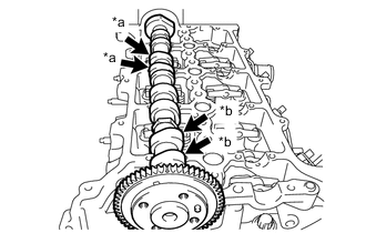
*a No. 3 Cylinder Cam Lobe *b No. 1 Cylinder Cam Lobe Place the No. 2 camshaft on the cylinder head sub-assembly as shown in the illustration so that the No. 1 and No. 3 cylinder cam lobes face upward.
-
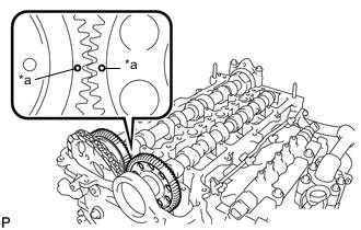
*a Dot Mark Align the camshaft and No. 2 camshaft timing mark (1 dot mark each).
-
Place the camshaft on the cylinder head sub-assembly.
-
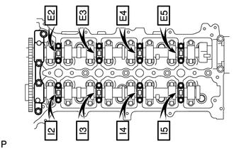
Set the 8 No. 3 camshaft bearing caps and No. 1 camshaft bearing cap on the camshafts as shown in the illustration.
Tech Tips
Check the marks and numbers on the camshaft bearing caps and place them in the proper position and direction.
-
Temporarily tighten the 20 bolts.
-
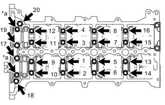
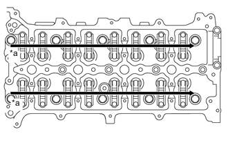
*a Oil Pipe Seat Uniformly tighten the bolts in several steps, in the order shown in the illustration.
- Torque:
- for 1 to 16
- 10 N*m { 102 kgf*cm, 7 ft.*lbf }
- for 17 to 20
- 21 N*m { 214 kgf*cm, 15 ft.*lbf }
-
Install the 2 oil pipe seats.
- Torque:
- 17 N*m { 173 kgf*cm, 13 ft.*lbf }
-
-
INSTALL CAMSHAFT TIMING SPROCKET
-
INSTALL OIL PUMP DRIVE GEAR
-
INSTALL NO. 1 CHAIN VIBRATION DAMPER
-
INSTALL CHAIN TENSIONER SLIPPER
-
INSTALL NO. 1 CHAIN TENSIONER ASSEMBLY
-
INSTALL SUPPLY PUMP ASSEMBLY
-
INSTALL TIMING CHAIN COVER SUB-ASSEMBLY