CAMSHAFT REMOVAL
PROCEDURE
-
REMOVE TIMING CHAIN COVER SUB-ASSEMBLY
-
REMOVE SUPPLY PUMP ASSEMBLY
-
REMOVE NO. 1 CHAIN TENSIONER ASSEMBLY
-
REMOVE CHAIN TENSIONER SLIPPER
-
REMOVE NO. 1 CHAIN VIBRATION DAMPER
-
REMOVE OIL PUMP DRIVE GEAR
-
REMOVE CAMSHAFT TIMING SPROCKET
-
REMOVE CRANKSHAFT TIMING SPROCKET
-
REMOVE CAMSHAFT
-
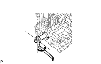
Using the crankshaft pulley bolt, set the No. 1 cylinder to 90° BTDC/compression.
-
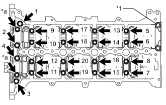
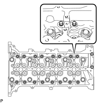
*1 No. 4 camshaft Bearing Cap *a Oil Pipe Seat Remove the 2 oil pipe seats.
-
Uniformly loosen the 20 bolts in several steps, in the order shown in the illustration and remove the bolts.
-
Remove the 8 No. 3 camshaft bearing caps and No. 1 camshaft bearing cap.
Tech Tips
Do not remove the No. 4 camshaft bearing cap.
-
Remove the camshaft and No. 2 camshaft.
-
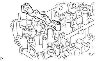
Remove the No. 2 camshaft bearing cap.
-
-
REMOVE NO. 1 VALVE ROCKER ARM SUB-ASSEMBLY
-
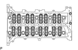
Remove the 16 No. 1 valve rocker arm sub-assemblies.
-
-
REMOVE VALVE LASH ADJUSTER ASSEMBLY
-
Remove the 16 valve lash adjuster assemblies from the cylinder head.
Tech Tips
Arrange the removed parts in the correct order.
-