ENGINE ASSEMBLY INSTALLATION

PROCEDURE
-
INSTALL ENGINE HANGERS
-
REMOVE ENGINE FROM ENGINE STAND
-
Using a chain block and engine sling device, secure the engine assembly.
Note
-
Adjust the angle of the sling device carefully to prevent the engine assembly or engine hangers from deforming or becoming damaged.
-
Servicing an engine assembly while it is hanging is dangerous. This can be done only when installing/removing the engine assembly to/from an engine stand.
-
-
Remove the engine assembly from the engine stand.
-
-
INSTALL FLYWHEEL SUB-ASSEMBLY
-
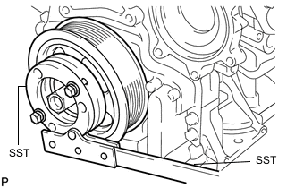
Hold the crankshaft pulley with SST.
- SST
- 09213-58014 ( 91551-80840 )
- 09330-00021
-
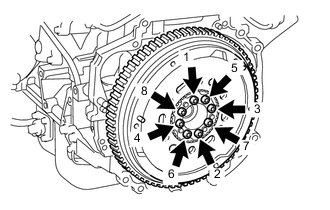
Using a T55 "TORX" socket wrench, install the flywheel sub-assembly with 8 new bolts and uniformly tighten the bolts in several steps in the sequence shown in the illustration.
- Torque:
- 70.6 N*m { 720 kgf*cm, 52 ft.*lbf }
Note
-
Do not reuse the flywheel sub-assembly installation bolts.
-
Be sure to check the tightening torque within 5 minutes of installation.
-
Do not impact or damage the flywheel sub-assembly installation bolts. Be sure to handle them carefully.
-
Make sure there is no oil on the bolts.
Tech Tips
Make sure that the seating surface of the flywheel sub-assembly installation bolts and installation surfaces of the crankshaft and flywheel sub-assembly are free from oil and foreign matter.
-
-
INSTALL CLUTCH DISC ASSEMBLY
-
INSTALL CLUTCH COVER ASSEMBLY
-
INSPECT AND ADJUST CLUTCH COVER ASSEMBLY
-
INSTALL MANUAL TRANSAXLE ASSEMBLY
-
INSTALL ENGINE WIRE
-
Install the engine wire to the engine assembly with transaxle.
-
-
INSTALL STIFFENER PLATE LH
-
INSTALL STIFFENER PLATE RH
-
INSTALL OIL PAN INSULATOR
-
INSTALL STARTER ASSEMBLY
-
INSTALL NO. 1 AIR TUBE
-
CONNECT ENGINE WIRE
-
INSTALL ENGINE MOUNTING INSULATOR LH
Tech Tips
Perform this procedure only when replacement of the engine mounting insulator LH is necessary.
-
Install the engine mounting insulator LH with the 4 bolts.
- Torque:
- 95 N*m { 969 kgf*cm, 70 ft.*lbf }
-
-
INSTALL ENGINE MOUNTING INSULATOR SUB-ASSEMBLY RH
Tech Tips
Perform this procedure only when replacement of the engine mounting insulator sub-assembly RH is necessary.
-
Install the engine mounting insulator sub-assembly RH with the 3 bolts.
- Torque:
- 95 N*m { 969 kgf*cm, 70 ft.*lbf }
-
Connect the cooler pipe clamp to the engine mounting insulator sub-assembly RH.
-
Install the cooler pipe clamp bracket to the engine mounting insulator sub-assembly RH with the bolt.
- Torque:
- 9.8 N*m { 100 kgf*cm, 87 in.*lbf }
-
Connect the cooler piping clamp to the engine mounting insulator sub-assembly RH.
-
Connect the radiator reservoir tank assembly with the 2 bolts.
- Torque:
- 5.0 N*m { 51 kgf*cm, 44 in.*lbf }
-
-
TEMPORARILY TIGHTEN REAR ENGINE MOUNTING INSULATOR
Tech Tips
Perform this procedure only when replacement of the rear engine mounting insulator is necessary.
-
Temporarily install the rear engine mounting insulator to the rear engine mounting bracket with the bolt.
-
-
TEMPORARILY TIGHTEN FRONT ENGINE MOUNTING INSULATOR
Tech Tips
Perform this procedure only when replacement of the front engine mounting insulator is necessary.
-
Temporarily install the front engine mounting insulator to the front engine mounting bracket with the through bolt and nut.
-
-
INSTALL ENGINE ASSEMBLY WITH TRANSAXLE
-
Set the engine assembly with transaxle on the engine lifter.
Note
Install a height adjustment attachment and plate lift attachment onto the engine assembly with transaxle.
-
Operate the engine lifter and lift the engine assembly with transaxle to the position where the engine mounting insulator LH and engine mounting insulator sub-assembly RH can be installed.
CAUTION:
Do not raise the engine assembly with transaxle more than necessary. If the engine assembly with transaxle is raised excessively, the vehicle may also be lifted up.
Note
While raising the engine assembly with transaxle into the vehicle, do not allow it to contact the vehicle.
-
Make sure that the engine assembly with transaxle is clear of all wiring and hoses.
-
While raising the engine assembly with transaxle into the vehicle, do not allow it to contact the vehicle.
-
-
Install the engine mounting insulator LH with the through bolt and nut.
- Torque:
- 56 N*m { 571 kgf*cm, 41 ft.*lbf }
Tech Tips
When tightening the through bolt, keep the nut from rotating.
-
*a Nut A *b Nut B Install the engine mounting insulator sub-assembly RH with the 2 bolts and 2 nuts.
- Torque:
- Bolt and Nut A
- 95 N*m { 969 kgf*cm, 70 ft.*lbf }
- Nut B
- 52 N*m { 530 kgf*cm, 38 ft.*lbf }
-
Install the front crossmember sub-assembly with the 4 bolts.
- Torque:
- 99 N*m { 1010 kgf*cm, 73 ft.*lbf }
-
Connect the front engine mounting insulator to the front crossmember sub-assembly with the 2 bolts.
- Torque:
- 95 N*m { 969 kgf*cm, 70 ft.*lbf }
-
-
REMOVE ENGINE HANGER
-
Remove the 2 bolts and No. 1 engine hanger and No. 2 engine hanger.
-
-
INSTALL FRONT SUSPENSION CROSSMEMBER SUB-ASSEMBLY
-
INSTALL FRONT SUSPENSION MEMBER REAR BRACE LH
-
INSTALL FRONT SUSPENSION MEMBER REAR BRACE RH
Tech Tips
Perform the same procedure as the LH side.
-
INSTALL FRONT SUSPENSION MEMBER REINFORCEMENT LH
-
INSTALL FRONT ENGINE MOUNTING BRACKET LOWER REINFORCEMENT (w/ Reinforcement)
-
FULLY TIGHTEN REAR ENGINE MOUNTING INSULATOR
-
Fully tighten the rear engine mounting insulator through bolt.
- Torque:
- 95 N*m { 969 kgf*cm, 70 ft.*lbf }
-
-
FULLY TIGHTEN FRONT ENGINE MOUNTING INSULATOR
-
Fully tighten the front engine mounting insulator through bolt and nut.
- Torque:
- 85 N*m { 867 kgf*cm, 63 ft.*lbf }
Tech Tips
Because the nut has its own stopper, do not turn the nut. Tighten the bolt with the nut secured
-
-
INSTALL FRONT DRIVE SHAFT ASSEMBLY
-
INSTALL FRONT EXHAUST PIPE ASSEMBLY
-
INSTALL FRONT CENTER FLOOR BRACE SUB-ASSEMBLY
-
INSTALL NO. 1 STEERING COLUMN HOLE COVER SUB-ASSEMBLY
-
INSTALL NO. 2 STEERING INTERMEDIATE SHAFT ASSEMBLY
-
INSTALL COLUMN HOLE COVER SILENCER SHEET
-
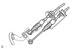
CONNECT CLUTCH RELEASE CYLINDER ASSEMBLY
-
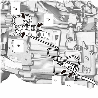
*a Bolt A *b Bolt B Connect the clutch release cylinder assembly and flexible hose bracket with the 5 bolts.
- Torque:
- Bolt A
- 8.0 N*m { 82 kgf*cm, 71 in.*lbf }
- Bolt B
- 12 N*m { 122 kgf*cm, 9 ft.*lbf }
-
-
CONNECT TRANSMISSION CONTROL CABLE ASSEMBLY
-
Install the transmission control cable assembly to the rear engine mounting insulator with the bolt.
- Torque:
- 5.0 N*m { 51 kgf*cm, 44 in.*lbf }
-
Install the transmission control cable assembly to the control cable bracket with 2 new clips.
-
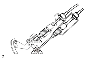
Install the transmission control cable assembly to the manual transaxle assembly with the 2 clips.
-
-
INSTALL COMPRESSOR ASSEMBLY WITH PULLEY (w/ Air Conditioning System)
-
CONNECT DISCHARGE HOSE SUB-ASSEMBLY (w/ Air Conditioning System)
-
CONNECT SUCTION HOSE SUB-ASSEMBLY (w/ Air Conditioning System)
-
INSTALL V-RIBBED BELT
-
INSTALL FRONT SUSPENSION MEMBER REINFORCEMENT RH
-
INSTALL INJECTOR DRIVER
-
CONNECT NO.2 RADIATOR HOSE
-
Connect the No. 2 radiator hose to the water inlet housing and slide the clip to secure it.
-
-
CONNECT WATER BY-PASS HOSE
-
Connect the water by-pass hose to the water inlet pipe and slide the clip to secure it.
-
-
INSTALL INTERCOOLER AIR HOSE
-
CONNECT NO. 1 RADIATOR HOSE
-
Connect the No. 1 radiator hose to the cylinder head sub-assembly and slide the clip to secure it.
-
-
CONNECT INLET HEATER WATER HOSE
-
Connect the inlet heater water hose to the cylinder head sub-assembly and slide the clip to secure it.
-
-
CONNECT OUTLET HEATER WATER HOSE
-
Connect the outlet heater water hose to the cylinder head sub-assembly and slide the clip to secure it.
-
-
CONNECT VACUUM PUMP HOSE
-
Connect the vacuum pump hose to the cylinder head sub-assembly and slide the clip to secure it.
-
-
CONNECT HOSES AND CONNECTORS
-
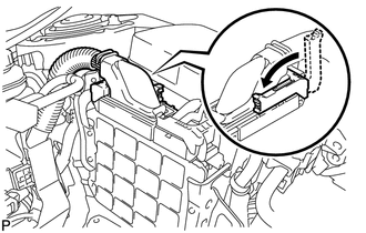
Connect the ECM connector and lower the lever.
Note
-
When connecting the connector, make sure that dirt, water and other foreign matter is not stuck between the connector and ECM.
-
Make sure that the lever is securely lowered.
-
-
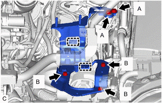
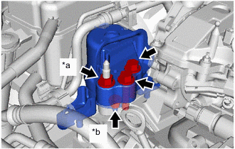
Install the air cleaner bracket with the fuel filter support and glow plug relay assembly with the 5 bolts.
- Torque:
- Bolt A
- 17.5 N*m { 178 kgf*cm, 13 ft.*lbf }
- Bolt B
- 7.0 N*m { 71 kgf*cm, 62 in.*lbf }
-
Engage the 2 clamps to the air cleaner bracket.
-
Connect the No. 3 engine wire to the manual transaxle assembly with the bolt.
- Torque:
- 12.5 N*m { 127 kgf*cm, 9 ft.*lbf }
-
Connect the wire harness to the engine room relay block with the 2 claws. Then install it with the 2 nuts and 3 connectors.
- Torque:
- 8.5 N*m { 87 kgf*cm, 75 in.*lbf }
-
Install the No. 1 engine room relay block cover to the engine room relay block.
-
-
INSTALL FUEL FILTER ASSEMBLY
-
INSTALL AIR CLEANER CASE SUB-ASSEMBLY
-
Install the air cleaner case sub-assembly with the 3 bolts.
- Torque:
- 7.0 N*m { 71 kgf*cm, 62 in.*lbf }
-
install the air cleaner filter element sub-assembly to the air cleaner case sub-assembly.
-
-
INSTALL AIR CLEANER CAP SUB-ASSEMBLY
-
Connect the air cleaner hose and slide the clip to secure it.
-
Lock the 2 lock clamps to install the air cleaner cap sub-assembly.
-
Connect the No. 2 ventilation hose and slide the clip to secure it.
-
Connect the mass air flow meter connector.
-
-
INSTALL NO. 3 AIR HOSE
-
CONNECT NO. 2 VACUUM TRANSMITTING HOSE ASSEMBLY
-
Connect the No. 2 vacuum transmitting hose assembly to the intake manifold and slide the clip to secure it.
-
-
INSTALL BATTERY CARRIER BRACKET SUB-ASSEMBLY
-
Install the battery carrier bracket sub-assembly with the 4 bolts.
- Torque:
- 18.5 N*m { 189 kgf*cm, 14 ft.*lbf }
-
Connect the 2 clamps and engine wire to the battery carrier bracket sub-assembly.
-
-
INSTALL BATTERY
-
Install the battery tray to the battery carrier bracket sub-assembly.
-
Install the battery insulator and battery.
-
Install the battery clamp sub-assembly and battery clamp bolt with the bolt and nut.
- Torque:
- Bolt
- 16.5 N*m { 168 kgf*cm, 12 ft.*lbf }
- Nut
- 3.5 N*m { 36 kgf*cm, 31 in.*lbf }
-
Connect the positive (+) cable to the positive (+) battery terminal with the nut.
- Torque:
- 5.4 N*m { 55 kgf*cm, 48 in.*lbf }
-
-
INSTALL DIFFERENTIAL PRESSURE SENSOR ASSEMBLY
-
ADD MANUAL TRANSAXLE OIL
-
INSPECT FOR MANUAL TRANSAXLE OIL LEAK
-
ADD ENGINE OIL
-
CONNECT CABLE TO NEGATIVE BATTERY TERMINAL
-
Connect the negative (-) cable to the negative (-) battery terminal.
- Torque:
- 5.4 N*m { 55 kgf*cm, 48 in.*lbf }
Note
When disconnecting the cable, some systems need to be initialized after the cable is reconnected
-
-
BLEED FUEL SYSTEM
-
ADD ENGINE COOLANT
-
PERFORM REGISTRATION
-
Perform registration of the injector compensation codes.
-
Perform registration of the pilot quantity learning.
-
-
PERFORM INITIALIZATION
-
Perform initialization of the crank time compensation reset function.
-
-
INSPECT FOR OIL LEAK
-
INSPECT FOR COOLANT LEAK
-
INSPECT FOR FUEL LEAK
-
INSPECT FOR EXHAUST GAS LEAK
-
INSTALL REAR ENGINE UNDER COVER LH
-
Install the rear engine under cover LH with the 5 clips.
-
-
INSTALL REAR ENGINE UNDER COVER RH
-
Install the rear engine under cover RH with the 5 clips.
-
-
INSTALL FRONT NO. 3 ENGINE UNDER COVER
-
INSTALL CENTER NO. 4 ENGINE UNDER COVER (w/ Cover)
-
Install the center No. 4 engine under cover with the 2 clips.
-
-
INSTALL NO. 1 ENGINE UNDER COVER
-
Install the No. 1 engine under cover with the 11 clips and 6 bolts.
-
-
INSTALL FRONT LOWER BUMPER ABSORBER
-
INSTALL NO. 1 ENGINE COVER
-
Engage the 4 clips to install the No. 1 engine cover.
Note
-
Be sure to engage the clips securely.
-
Do not apply excessive force or hit the No. 1 engine cover to engage the clips. This may cause the No. 1 engine cover to break.
-
-
-
INSTALL NO. 2 RADIATOR AIR GUIDE
-
Install the No. 2 radiator air guide with the 7 clips.
-
-
INSTALL OUTER COWL TOP PANEL
-
INSTALL FRONT WHEELS
-
INSPECT ENGINE IDLE SPEED
-
CHARGE AIR CONDITIONING SYSTEM WITH REFRIGERANT
-
WARM UP ENGINE
-
INSPECT FOR REFRIGERANT LEAK
-
ADJUST FRONT WHEEL ALIGNMENT
-
CHECK ABS SPEED SENSOR SIGNAL