ECD SYSTEM, Diagnostic DTC:P052F
| DTC Code | DTC Name |
|---|---|
| P052F | Glow Plug Control Module 1 System Voltage |
DESCRIPTION
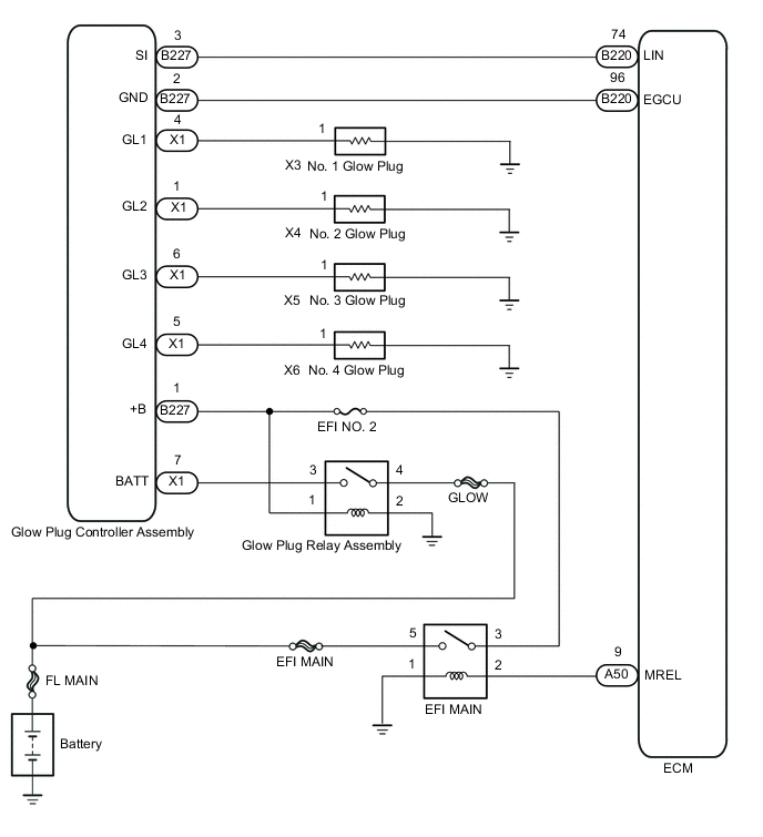
The glow plug controller assembly has a built-in voltage output stage during glow plug activation. The ECM activates the glow plugs by sending a signal indicating the required temperature to the glow plug controller assembly.
Also, the ECM sends control signals to the glow plug controller assembly via the LIN bus based on the values from various sensors.
When the glow plug control controller assembly detects a problem in the pre-heat system, it sends a report to the ECM via the LIN bus. The malfunction report is then stored inside the ECM
| DTC No. | Detection Item | DTC Detection Condition | Trouble Area | MIL | Memory |
|---|---|---|---|---|---|
| P052F | Glow Plug Control Module 1 System Voltage | When glow plug controller assembly power supply voltage is low for 1.2 seconds or more. (3 trip detection logic) |
|
Does not come on | DTC stored |
WIRING DIAGRAM
CAUTION / NOTICE / HINT
Note
-
When replacing the ECM, the ECM needs registration and initialization.
-
Inspect the fuses for circuits related to this system before performing the following inspection procedure.
Tech Tips
-
When the ECM must be replaced, before replacing the ECM, perform the "Learning Values Save" function using the GTS. Then after installing the new ECM, perform all of the initialization/registrations for the "Learning Values Write" function by following the instructions shown on the GTS display.
-
Read freeze frame data using the GTS. Freeze frame data records the engine condition when malfunctions are detected. When troubleshooting, freeze frame data can help determine if the vehicle was moving or stationary, if the engine was warmed up or not, and other data from the time the malfunction occurred.
PROCEDURE
-
INSPECT GLOW PLUG RELAY ASSEMBLY
-
Inspect the glow plug relay assembly.
Result Proceed to OK NG
NG 
REPLACE GLOW PLUG RELAY ASSEMBLY Click here
OK 
-
-
CHECK GLOW PLUG CONTROLLER ASSEMBLY (BATT)
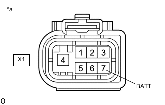
*a Front view of wire harness connector
(to Glow Plug Controller Assembly)
-
Disconnect the glow plug controller assembly connector.
-
Measure the voltage according to the value(s) in the table below.
Standard Voltage Tester Connection Condition Specified Condition X1-7 (BATT) - Body ground Always 11 to 14 V Result Proceed to OK NG
NG
CHECK HARNESS AND CONNECTOR (GLOW PLUG CONTROLLER - RELAY - BATTERY) Click here
OK
-
-
CHECK GLOW PLUG CONTROLLER ASSEMBLY (POWER SOURCE CIRCUIT)
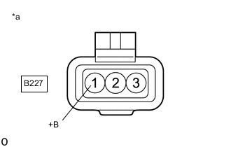
*a Front view of wire harness connector
(to Glow Plug Controller Assembly)
-
Disconnect the glow plug controller assembly connector.
-
Turn the ignition switch to ON.
-
Measure the voltage according to the value(s) in the table below.
Standard Voltage Tester Connection Switch Condition Specified Condition B227-1 (+B) - Body ground Ignition switch ON 11 to 14 V Result Proceed to OK NG
NG
CHECK HARNESS AND CONNECTOR (GLOW PLUG CONTROLLER ASSEMBLY - EFI MAIN RELAY) Click here
OK
-
-
CHECK HARNESS AND CONNECTOR (GLOW PLUG CONTROLLER ASSEMBLY - ECM)
-
Disconnect the glow plug controller assembly connector.
-
Disconnect the ECM connector.
-
Measure the resistance according to the value(s) in the table below.
Standard Resistance Tester Connection Condition Specified Condition B227-2 (GND) - B220-96 (EGCU) Always Below 1 Ω B227-2 (GND) or B220-96 (EGCU) - Body ground Always 10 kΩ or higher Result Proceed to OK NG
NG
GO TO STEP 11 Click here
OK
-
-
REPLACE GLOW PLUG CONTROLLER ASSEMBLY
-
Replace the glow plug controller assembly.
Result Proceed to NEXT
NEXT
-
-
CONFIRM WHETHER MALFUNCTION HAS BEEN SUCCESSFULLY REPAIRED
-
Connect the GTS to the DLC3.
-
Turn the ignition switch to ON and turn the GTS on.
-
Clear the DTCs.
Powertrain > Engine and ECT > Clear DTCs -
Turn the ignition switch off and wait for 60 seconds or more [A].
-
Perform road test [B].
-
Repeat [A] and [B] for the number of trips detected.
-
Enter the following menus: Powertrain / Engine and ECT / Trouble Codes.
Powertrain > Engine and ECT > Trouble Codes -
Confirm that the DTC is not output again.
Result Proceed to OK NG
OK 
END
NG
-
-
REPLACE ECM
-
Replace the ECM.
Result Proceed to NEXT
NEXT
GO TO STEP 13 Click here
-
-
CHECK HARNESS AND CONNECTOR (GLOW PLUG CONTROLLER ASSEMBLY - EFI MAIN RELAY)
-
Disconnect the glow plug controller assembly connector.
-
Remove the EFI MAIN relay from the engine room relay block and junction block.
-
Measure the resistance according to the value(s) in the table below.
Standard Resistance Tester Connection Condition Specified Condition B227-1 (+B) - 3 (EFI MAIN relay holder) Always Below 1 Ω B227-1 (+B) or 3 (EFI MAIN relay holder) - Body ground Always 10 kΩ or higher Result Proceed to OK NG
OK
GO TO STEP 10 Click here
NG
GO TO STEP 11 Click here
-
-
CHECK HARNESS AND CONNECTOR (GLOW PLUG CONTROLLER - RELAY - BATTERY)
-
Disconnect the glow plug controller assembly connector.
-
Remove the glow plug relay assembly.
-
Remove the EFI MAIN relay from the engine room relay block and junction block.
-
Measure the resistance according to the value(s) in the table below.
Standard Resistance Tester Connection Condition Specified Condition X1-7 (BATT) - 3 (glow plug relay holder) Always Below 1 Ω 4 (glow plug relay holder) - positive (+) battery terminal Always Below 1 Ω 1 (glow plug relay holder) - 3 (EFI MAIN relay holder) Always Below 1 Ω 2 (glow plug relay holder) - Body ground Always Below 1 Ω X1-7 (BATT) or 3 (glow plug relay holder) - Body ground Always 10 kΩ or higher 4 (glow plug relay holder) or positive (+) battery terminal - Body ground Always 10 kΩ or higher 1 (glow plug relay holder) or 3 (EFI MAIN relay holder) - Body ground Always 10 kΩ or higher Result Proceed to OK NG
NG
REPAIR OR REPLACE HARNESS OR CONNECTOR Click here
OK
-
-
CHECK ECM POWER SOURCE CIRCUIT
-
Check the ECM power source circuit.
Tech Tips
If there are no malfunctions in the ECM power source circuit, recharge or replace the battery.
Result Proceed to NEXT
NEXT
GO TO STEP 13 Click here
-
-
REPAIR OR REPLACE HARNESS OR CONNECTOR
-
Repair or replace the harness or connector.
Result Proceed to NEXT
NEXT
GO TO STEP 13 Click here
-
-
REPLACE GLOW PLUG RELAY ASSEMBLY
-
Replace the glow plug relay assembly.
Result Proceed to NEXT
NEXT
-
-
CONFIRM WHETHER MALFUNCTION HAS BEEN SUCCESSFULLY REPAIRED
-
Connect the GTS to the DLC3.
-
Turn the ignition switch to ON and turn the GTS on.
-
Clear the DTCs.
Powertrain > Engine and ECT > Clear DTCs -
Turn the ignition switch off and wait for 60 seconds or more [A].
-
Perform road test [B].
-
Repeat [A] and [B] for the number of trips detected.
-
Enter the following menus: Powertrain / Engine and ECT / Trouble Codes.
Powertrain > Engine and ECT > Trouble Codes -
Confirm that the DTC is not output again.
Result Proceed to NEXT
NEXT
END
-