ECD SYSTEM, Diagnostic DTC:P0471, P0472, P0473
| DTC Code | DTC Name |
|---|---|
| P0471 | Exhaust Pressure Sensor "A" Circuit Range / Performance |
| P0472 | Exhaust Pressure Sensor "A" Circuit Low |
| P0473 | Exhaust Pressure Sensor "A" Circuit High |
DESCRIPTION
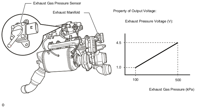
The exhaust gas pressure sensor is fixed to the engine by a holder to protect it from high temperatures.
The exhaust gas pressure sensor is connected to the exhaust manifold via a hose and pipe, and detects the exhaust gas pressure before exhaust turbocharger.
The exhaust gas pressure sensor is supplied with 5 V from the ECM and has a measurement range between 100 kPa (1.01 bar) to 500 kPa (5.1 bar). This is equivalent to 1.0 to 4.5 V.
| DTC No. | Detection Item | DTC Detection Condition | Trouble Area | MIL | Memory |
|---|---|---|---|---|---|
| P0471 | Exhaust Pressure Sensor "A" Circuit Range / Performance | Either condition is met (3 trip detection logic):
Tech Tips The difference of the standard pressure value (turbo pressure and ambient pressure) is 60 mbar (6 kPa) or less. |
|
Comes on | DTC stored |
| P0472 | Exhaust Pressure Sensor "A" Circuit Low | Exhaust gas pressure sensor output voltage is 0.2 V or less. (3 trip detection logic) |
|
Comes on | DTC stored |
| P0473 | Exhaust Pressure Sensor "A" Circuit High | Exhaust gas pressure sensor output voltage is 4.9 V or more. (3 trip detection logic) |
|
Comes on | DTC stored |
| DTC No. | Data List |
|---|---|
| P0471 P0472 P0473 |
Sensed Value of the Pressure at TrbnUs Absolute Turbine Upstream Pressure |
WIRING DIAGRAM
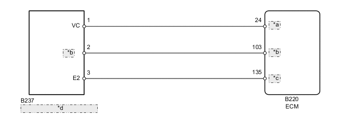
| *a | VCPE |
| *b | PEXM |
| *c | EPEM |
| *d | Exhaust Gas Pressure Sensor |
CAUTION / NOTICE / HINT
Tech Tips
-
When the ECM must be replaced, before replacing the ECM, perform the "Learning Values Save" function using the GTS. Then after installing the new ECM, perform all of the initialization/registrations for the "Learning Values Write" function by following the instructions shown on the GTS display.
-
Read freeze frame data using the GTS. Freeze frame data records the engine condition when malfunctions are detected. When troubleshooting, freeze frame data can help determine if the vehicle was moving or stationary, if the engine was warmed up or not, and other data from the time the malfunction occurred.
PROCEDURE
-
CHECK HARNESS AND CONNECTOR (EXHAUST GAS PRESSURE SENSOR - ECM)
-
Disconnect the exhaust gas pressure sensor connector.
-
Disconnect the ECM connector.
-
Measure the resistance according to the value(s) in the table below.
Standard Resistance Tester Connection Condition Specified Condition B237-1 (VC) - B220-24 (VCPE) Always Below 1 Ω B237-2 (PEXM) - B220-103 (PEXM) Always Below 1 Ω B237-3 (E2) - B220-135 (EPEM) Always Below 1 Ω B237-1 (VC) or B220-24 (VCPE) - Body ground Always 10 kΩ or higher B237-2 (PEXM) or B220-103 (PEXM) - Body ground Always 10 kΩ or higher B237-3 (E2) or B220-135 (EPEM) - Body ground Always 10 kΩ or higher Result Proceed to OK NG
NG 
REPAIR OR REPLACE HARNESS OR CONNECTOR Click here
OK 
-
-
CHECK HARNESS AND CONNECTOR (VC VOLTAGE)
-
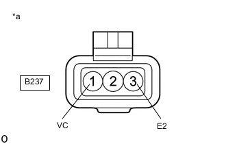
*a Front view of wire harness connector
(to Exhaust Gas Pressure Sensor)
Disconnect the exhaust gas pressure sensor connector.
-
Turn the ignition switch to ON.
-
Measure the voltage according to the value(s) in the table below.
Standard Voltage Tester Connection Switch Condition Specified Condition B237-1 (VC) - B237-3 (E2) Ignition switch ON 4.5 to 5.5 V Result Proceed to OK NG
NG
REPLACE ECM Click here
OK
-
-
REPLACE EXHAUST GAS PRESSURE SENSOR
-
Replace the exhaust gas pressure sensor.
Result Proceed to NEXT
NEXT
-
-
CHECK WHETHER DTC OUTPUT RECURS (DTC P0471, P0472 OR P0473)
-
Connect the GTS to the DLC3.
-
Turn the ignition switch to ON and turn the GTS on.
-
Clear the DTCs.
Powertrain > Engine and ECT > Clear DTCs -
Turn the ignition switch off and wait for 60 seconds or more [A].
-
Perform road test [B].
-
Repeat [A] and [B] for the number of trips detected.
-
Enter the following menus: Powertrain / Engine and ECT / Trouble Codes.
Powertrain > Engine and ECT > Trouble Codes -
Read the DTCs.
Result Result Proceed to No DTC output A DTC P0471, P0472 or P0473 B
A 
END
B
-
-
REPLACE ECM
-
Replace the ECM.
Result Proceed to NEXT
NEXT
GO TO STEP 7 Click here
-
-
REPAIR OR REPLACE HARNESS OR CONNECTOR
-
Repair or replace the harness or connector.
Result Proceed to NEXT
NEXT
-
-
CONFIRM WHETHER MALFUNCTION HAS BEEN SUCCESSFULLY REPAIRED
-
Connect the GTS to the DLC3.
-
Turn the ignition switch to ON and turn the GTS on.
-
Clear the DTCs.
Powertrain > Engine and ECT > Clear DTCs -
Turn the ignition switch off and wait for 60 seconds or more [A].
-
Perform road test [B].
-
Repeat [A] and [B] for the number of trips detected.
-
Enter the following menus: Powertrain / Engine and ECT / Trouble Codes.
Powertrain > Engine and ECT > Trouble Codes -
Confirm that the DTC is not output again.
Result Proceed to NEXT
NEXT
END
-