CONTINUOUSLY VARIABLE VALVE LIFT CONTROLLER REMOVAL
PROCEDURE
-
REMOVE NO. 2 CYLINDER HEAD COVER
-
REMOVE AIR CLEANER CAP SUB-ASSEMBLY
-
REMOVE BATTERY
-
DISCONNECT ENGINE WIRE
-
Disengage the 9 clamps, and then disconnect the connectors.
-
Remove the 3 bolts and 2 nuts, and then disconnect the engine wire.
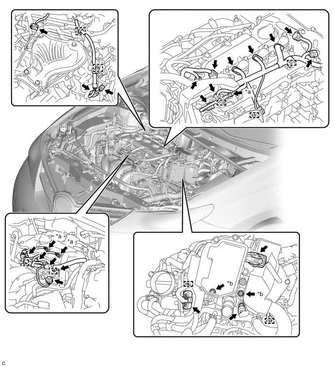
*a Bolt *b Nut
-
-
REMOVE IGNITION COIL ASSEMBLY
-
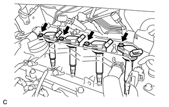
Remove the 4 bolts and 4 ignition coil assemblies.
-
-
REMOVE AIR TUBE
-
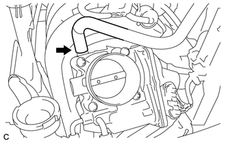
Disconnect the union to connector tube hose.
-
Disconnect the No. 2 air hose and No. 1 fuel vapor feed hose.
-
Remove the 2 bolts and air tube from the cylinder head cover sub-assembly.
-
-
REMOVE CYLINDER HEAD COVER SUB-ASSEMBLY
-
REMOVE CYLINDER HEAD COVER GASKET
-
REMOVE CONTINUOUSLY VARIABLE VALVE LIFT CONTROLLER ASSEMBLY
-
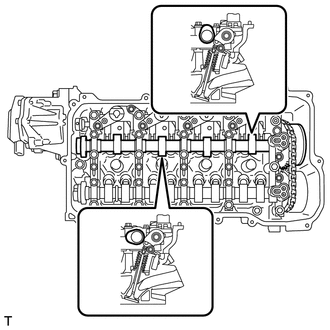
Using a screwdriver, slide the valve lift control actuator connector clip from the valve lift control actuator connector.
Note
Slide only the upper part of the valve lift control actuator connector clip, as the straight pin will fall out from the bottom if the valve lift control actuator connector clip is completely removed.
-
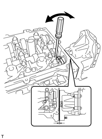
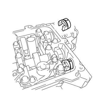
Rotate the crankshaft clockwise until the intake camshaft position at the No. 1 cylinder and No. 3 cylinder is as shown in the illustration.
Tech Tips
If the camshaft position is not as shown in the illustration, rotate the crankshaft clockwise again so that the camshaft is aligned as shown in the illustration.
-
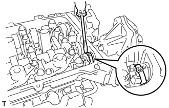
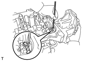
Using a screwdriver, lightly pry the valve lift control actuator connector to make a space between the continuously variable valve lift controller assembly and camshaft housing.
Note
-
Do not forcibly pry the valve lift control actuator connector.
-
Do not damage the camshaft housing or camshaft bearing cap.
-
-
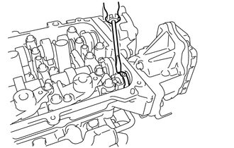
Using a magnet hand, remove the straight pin from the valve lift control actuator connector.
Note
Do not drop the straight pin into the engine.
Tech Tips
The pin can be removed by utilizing the space between the continuously variable valve lift controller assembly and camshaft housing to move the continuously variable valve lift controller assembly so that there is no load on the pin.
-
Using a screwdriver, remove the valve lift control actuator connector clip from the valve lift control actuator connector.
Note
Do not drop the valve lift control actuator connector clip into the engine.
-
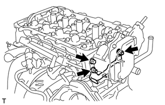
Remove the bolt, 2 nuts and wire harness clamp bracket.
-
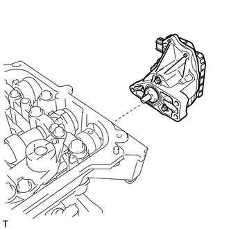
Remove the continuously variable valve lift controller assembly from the camshaft housing.
-
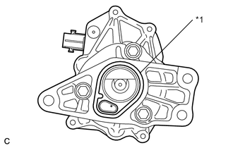
*1 O-ring Remove the O-ring from the continuously variable valve lift controller assembly.
-
Remove the valve lift control actuator connector from the valve rocker shaft.
-