STARTER REASSEMBLY
PROCEDURE
-
INSTALL STARTER CLUTCH SUB-ASSEMBLY
-
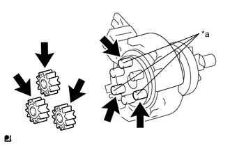
*a Pin without Depression 
High-temperature Grease Apply high-temperature grease to the 3 planet gears and starter clutch sub-assembly.
Tech Tips
Apply approximately 0.5 g of high-temperature grease to the planet gear section, end section and pins without depressions.
-

*a Pin without Depression Install the 3 planetary gears to the pins without depressions on the starter clutch sub-assembly.
-
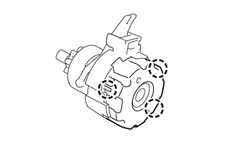
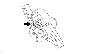
Engage the 3 claws and install the shock absorber to the starter clutch sub-assembly.
-
High-temperature Grease Apply high-temperature grease to the drive lever contact surface.
Tech Tips
Apply approximately 0.1 g of high-temperature grease to each section.
-
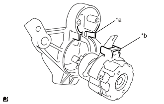
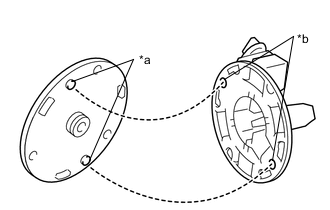
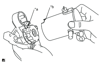
*a Depression *b Protrusion Align the depression of the starter drive housing with the protrusion of the starter clutch sub-assembly and install the starter clutch sub-assembly.
-
Install the rubber seal to the starter drive housing.
-
-
INSTALL STARTER BRUSH HOLDER ASSEMBLY
-
*a Protrusion *b Depression Install the commutator end frame to the starter brush holder assembly as shown in the illustration.
Tech Tips
If the bolt holes are misaligned, the through bolts cannot be installed.
-
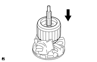
Spread the brushes on the starter brush holder assembly, and install the starter armature assembly to the starter brush holder assembly.
-
-
INSTALL STARTER ARMATURE ASSEMBLY
-
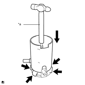
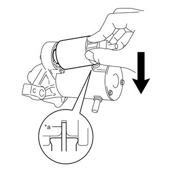
*a Hammer While holding down the starter armature assembly and the starter brush holder assembly with the handle of a hammer, install the starter yoke assembly.
Tech Tips
The starter armature assembly will be attracted by the magnetic field of the starter yoke assembly, so hold the starter armature assembly with the handle of the hammer.
-
-
INSTALL STARTER YOKE ASSEMBLY
-
*a Protrusion *b Cutout Align the cutout of the starter yoke assembly with the protrusion of the starter clutch sub-assembly.
-
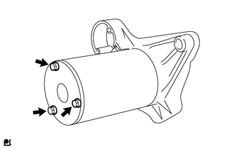
Using a 7 mm socket driver, install the starter yoke assembly with the 3 through bolts.
- Torque:
- 3.0 N*m { 31 kgf*cm, 27 in.*lbf }
-
-
INSTALL MAGNET STARTER SWITCH ASSEMBLY
-
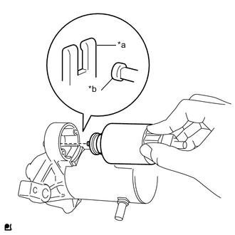
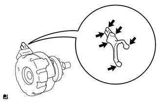
*a Drive Lever *b Hook Catch the hook on the magnet starter switch assembly on the drive lever from the top of the lever.
-
*a Terminal C While pushing down the rear of the magnet starter switch assembly, connect it to terminal C.
Note
-
Connect the magnet starter switch assembly securely to terminal C.
-
Check that the parts are free of foreign matter, oil, or grease.
-
-
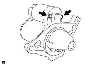
using a 7 mm socket driver, install the magnet starter switch assembly with the 2 bolts.
- Torque:
- 3.0 N*m { 31 kgf*cm, 27 in.*lbf }
-