MASS AIR FLOW METER INSPECTION
PROCEDURE
-
INSPECT MASS AIR FLOW METER SUB-ASSEMBLY
-
Check the output voltage.
-
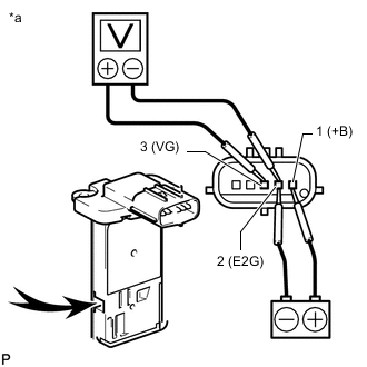
*a Component without harness connected
(Mass Air Flow Meter Sub-assembly)

Air Connect a battery positive (+) lead to terminal 1 (+B) and negative (-) lead to terminal 2 (E2G).
Note
While using the battery during inspection, do not bring the positive and negative tester probes too close to each other as a short circuit may occur.
-
Connect the positive (+) tester probe to terminal 3 (VG) and negative (-) tester probe to terminal 2 (E2G).
-
Blow air into the mass air flow meter sub-assembly and check that the voltage fluctuates.
If the result is not as specified, replace the mass air flow meter sub-assembly.
-
-
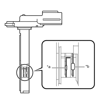
*a Platinum Hot Wire (Heater) *b Temperature Sensor (Thermistor) Perform a visual check for any foreign matter on the platinum hot wire (heater) and temperature sensor (thermistor) of the mass air flow meter sub-assembly shown in the illustration.
OK There is no foreign matter. If the result is not as specified, replace the mass air flow meter sub-assembly.
-
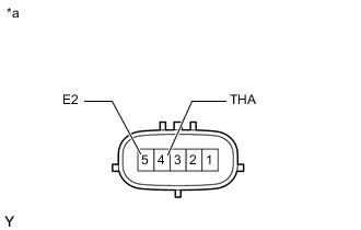
*a Component without harness connected
(Mass Air Flow Meter Sub-assembly)
Measure the resistance according to the value(s) in the table below.
Standard Resistance Tester Connection Condition Specified Condition 4 (THA) - 5 (E2) -20°C (-4°F) 12.5 to 16.9 kΩ 20°C (68°F) 2.19 to 2.67 kΩ 60°C (140°F) 0.50 to 0.68 kΩ If the result is not as specified, replace the mass air flow meter sub-assembly.
-