CAMSHAFT OIL CONTROL VALVE(for Intake Side) REMOVAL
PROCEDURE
-
REMOVE FRONT WHEEL RH
-
REMOVE REAR ENGINE UNDER COVER RH
-
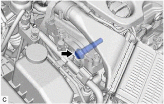
REMOVE CAMSHAFT TIMING OIL CONTROL SOLENOID ASSEMBLY (for Intake Side)
-
SET NO. 1 CYLINDER TO TDC/COMPRESSION
-
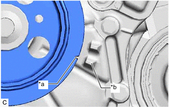
*a Timing Mark (Cutout) *b Protrusion Turn the crankshaft pulley clockwise until its timing mark (cutout) is aligned with the protrusion on the timing chain cover assembly as shown in the illustration.
-
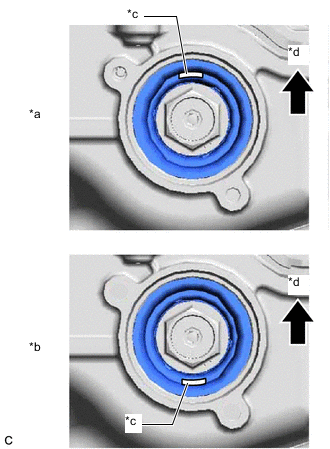
*a Correct *b Incorrect *c Cutout *d Up Check that the cutout of the camshaft timing gear assembly is at the top.
Tech Tips
If the cutout of the camshaft timing gear assembly is not at the top, turn the crankshaft 360° clockwise and align the timing mark (cutout) of the crankshaft pulley with the protrusion on the timing chain cover assembly again.
-
-
REMOVE CAMSHAFT TIMING GEAR BOLT
-
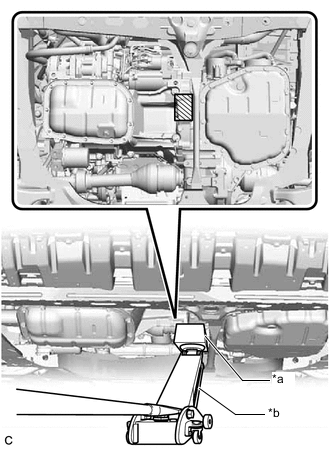
*a Wooden Block *b Jack 
Wooden Block Placement Location Support the engine using a jack and wooden block.
Note
Make sure to set the jack as shown in the illustration. Do not place the jack under the oil pan.
-
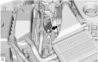
Remove the bolt from the engine mounting insulator sub-assembly RH.
-
While holding the crankshaft pulley, remove the camshaft timing gear bolt.
Note
-
If the camshaft timing gear bolt has been struck or dropped, replace it.
-
Do not turn the crankshaft pulley after removing the camshaft timing gear bolt.
-
-