ECD SYSTEM(w/o Glow Plug Controller), Diagnostic DTC:P244A
| DTC Code | DTC Name |
|---|---|
| P244A | Diesel Particulate Filter Differential Pressure Too Low |
DESCRIPTION
Refer to DTC P2454.
Tech Tips
If the DPF catalytic converter has melted or is removed due to a modification, the ECM interprets this as an abnormal pressure difference and DTC P244A will be stored and the MIL will be illuminated.
| DTC No. | Detection Item | DTC Detection Condition | Trouble Area | MIL | Memory |
|---|---|---|---|---|---|
| P244A | Diesel Particulate Filter Differential Pressure Too Low | The maximum differential pressure is threshold or less while engine is running (2 trip detection logic) |
|
Comes on | DTC stored |
| DTC No. | DTC Detection Drive Pattern |
|---|---|
| P244A | 20 seconds have elapsed since engine stopped |
| DTC No. | Data List |
|---|---|
| P244A | DPF Differential Pressure |
Tech Tips
-
DTC P2454 (Differential pressure sensor circuit low) and/or DTC P2455 (Differential pressure sensor high) will be present if there is an open or short in the differential pressure sensor circuit.
-
This DTC may also be stored due to the fail-safe operation of other DTCs.
CAUTION / NOTICE / HINT
Note
When replacing the ECM and/or DPF catalyst, perform ECM Initialization and Registration.
Tech Tips
-
When the ECM must be replaced, before replacing the ECM, perform the "Learning Values Save" function using the GTS. Then after installing a new ECM, perform all of the initialization and registration procedures for the "Learning Values Write" function by following the instructions shown on the GTS display.
-
Read freeze frame data using the GTS. Freeze frame data records the engine condition when malfunctions are detected. When troubleshooting, freeze frame data can help determine if the vehicle was moving or stationary, if the engine was warmed up or not, and other data from the time the malfunction occurred.
-
Check the DPF Differential Pressure using the GTS by entering the following menus: Powertrain / Engine and ECT / Data List / DPF Differential Pressure.
DPF Differential Pressure (Reference Value) Condition DPF Differential Pressure Idling (warm up the engine) -0.204 kPa Running without load (2500 rpm) 0.296 kPa Running without load (4000 rpm) 0.699 kPa
PROCEDURE
-
CHECK ANY OTHER DTCS OUTPUT (IN ADDITION TO DTC P244A)
-
Connect the GTS to the DLC3.
-
Turn the ignition switch to ON and turn the GTS on.
-
Enter the following menus: Powertrain / Engine and ECT / Trouble Codes.
-
Read the DTCs.
Powertrain > Engine and ECT > Trouble CodesResult Result Proceed to DTC P244A is output A DTC P244A and other DTCs are output B Tech Tips
If DTCs other than P244A are output, perform troubleshooting for those DTCs first.
B 
GO TO DTC CHART Click here
A 
-
-
CHECK CONNECTION OF VACUUM TRANSMITTING HOSE ASSEMBLY (DIFFERENTIAL PRESSURE SENSOR - VACUUM TRANSMITTING PIPE)
CAUTION:
Be careful of being burned by exhaust gases during the following inspection.
Note
-
Confirm the paint marks on the vacuum transmitting hoses before disconnecting them.
-
Check that the vacuum transmitting hose connections are on the correct side of the DPF/DPNR catalytic converter.
-
Disconnect both vacuum transmitting hoses (upstream and downstream) on the differential pressure sensor side.
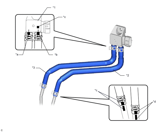
*1 Differential Pressure Sensor *2 Vacuum Transmitting Hose (for upstream) *3 No. 2 Vacuum Transmitting Hose (for downstream) - - *a Marked: Yellow *b Marked: Pink *c Marked: Red *d Marked: Orange -
Start the engine.
-
Check if there is exhaust gas pulsation from both vacuum transmitting hoses while the engine is idling.
OK The vacuum transmitting hoses connections are correct and there is no leak or blockage. Result Proceed to OK NG
NG 
REPLACE CLOGGED PARTS Click here
OK
-
-
CHECK EXHAUST SYSTEM
-
Check for exhaust gas leak from the exhaust system.
-
Check for exhaust system modifications.
OK No exhaust gas leak and no modifications. Result Proceed to OK NG
NG
REPAIR OR REPLACE EXHAUST SYSTEM Click here
OK
-
-
INSPECT DIFFERENTIAL PRESSURE SENSOR
-
Inspect the differential pressure sensor.
Standard Approximately the same pressure as the applied pressure is indicated. Tech Tips
The DPF Differential Pressure displayed is a value that does not reflect the zero point adjustment. Therefore the displayed value will be about +/-0.3 kPa even if the applied differential pressure is 0 kPa.
Result Proceed to OK NG
NG
REPLACE DIFFERENTIAL PRESSURE SENSOR Click here
OK
-
-
PERFORM DIFFERENTIAL PRESSURE SENSOR LEARNING
-
Start the engine and allow it to idle until the engine coolant temperature reaches 75°C (167°F) or higher (A).
-
Turn the ignition switch off and wait for 30 seconds or more (B).
-
Repeat the above procedures (A) and (B) 3 times.
Tech Tips
Procedures (A) and (B) must be repeated 3 times to complete the differential pressure sensor learning process.
Result Proceed to NEXT
NEXT
-
-
READ VALUE USING GTS (DPF DIFFERENTIAL PRESSURE)
-
Connect the GTS to the DLC3.
-
Turn the ignition switch to ON and turn the GTS on.
-
Enter the following menus: Powertrain / Engine and ECT / Data List / DPF Differential Pressure.
Powertrain > Engine and ECT > Data ListTester Display DPF Differential Pressure -
Read the value.
-
Start the engine.
-
Run the engine at 4500 rpm without load.
-
Compare the value at 4500 rpm with the value when the ignition switch is first turned ON.
Tech Tips
When reading the values of Data List, confirm that PM regeneration is not activated (value of "After Injection Period" is 0) by entering the following menus: Powertrain / Engine and ECT / Data List / After Injection Period.
If PM regeneration is activated (value of "After Injection Period" is not 0), drive the vehicle until the PM regeneration is complete (value of "After Injection Period" becomes 0).
Standard "DPF Differential Pressure at 4500 rpm" - "DPF Differential Pressure at ignition switch ON" is 1.0 kPa or higher. Result Result Proceed to Less than 1.0 kPa A 1.0 kPa or higher B
B
GO TO STEP 10 Click here
A
-
-
CHECK WHETHER DTC OUTPUT RECURS (DTC P244A)
-
Connect the GTS to the DLC3.
-
Turn the ignition switch to ON and turn the GTS on.
-
Clear the DTCs.
Powertrain > Engine and ECT > Clear DTCs -
Turn the ignition switch off and wait for 30 seconds.
-
Start the engine.
-
Drive the vehicle at a vehicle speed of approximately 100 km/h (62 mph) for 10 minutes or more.
CAUTION:
When performing the confirmation driving pattern, obey all speed limits and traffic laws.
Tech Tips
-
When reading the values of the Data List, confirm that PM regeneration is not activated (value of "After Injection Period" is 0).
-
PM Accumulation Ratio" will be more than 14%.
-
-
Turn the ignition switch off and wait for 30 seconds.
-
Turn the ignition switch to ON and turn the GTS on.
-
Enter the following menus: Powertrain / Engine and ECT / Trouble Codes / Pending.
-
Read the pending DTCs.
Powertrain > Engine and ECT > Trouble CodesTech Tips
Perform the following procedure using the GTS to determine whether or not the DTC judgment has been carried out.
-
Enter the following menus: Powertrain / Engine and ECT / Utility / All Readiness.
Powertrain > Engine and ECT > UtilityTester Display All Readiness -
Input DTC P244A.
-
Check that STATUS is NORMAL. If STATUS is INCOMPLETE or N/A, repeat the procedures (e) and (j).
Result Result Proceed to NORMAL A ABNORMAL B
-
A
CHECK FOR INTERMITTENT PROBLEMS Click here
B
-
-
REPLACE NO. 2 EXHAUST MANIFOLD CONVERTER SUB-ASSEMBLY (DPF CATALYTIC CONVERTER)
-
Replace the No. 2 exhaust manifold converter sub-assembly.
Result Proceed to NEXT
NEXT
-
-
PERFORM INITIALIZATION (DPF DETERIORATION RECORD)
-
Reset the DPF deterioration record.
Result Proceed to NEXT
NEXT
-
-
CONFIRM WHETHER MALFUNCTION HAS BEEN SUCCESSFULLY REPAIRED
-
Connect the GTS to the DLC3.
-
Turn the ignition switch to ON and turn the GTS on.
-
Clear the DTCs.
Powertrain > Engine and ECT > Clear DTCs -
Turn the ignition switch off and wait for 30 seconds.
-
Start the engine.
-
Drive the vehicle at a vehicle speed of approximately 100 km/h (62 mph) for 10 minutes or more.
CAUTION:
When performing the confirmation driving pattern, obey all speed limits and traffic laws.
Tech Tips
-
When reading the values of the Data List, confirm that PM regeneration is not activated (value of "After Injection Period" is 0).
-
"PM Accumulation Ratio" will be more than 14%.
-
-
Turn the ignition switch off and wait for 30 seconds.
-
Turn the ignition switch to ON and turn the GTS on.
-
Enter the following menus: Powertrain / Engine and ECT / Trouble Codes / Pending.
-
Confirm that the pending DTC is not output again.
Powertrain > Engine and ECT > Trouble CodesTech Tips
Perform the following procedure using the GTS to determine whether or not the DTC judgment has been carried out.
-
Enter the following menus: Powertrain / Engine and ECT / Utility / All Readiness.
Powertrain > Engine and ECT > UtilityTester Display All Readiness -
Input DTC P244A.
-
Check that STATUS is NORMAL. If STATUS is INCOMPLETE or N/A, repeat the procedures (f) and (j).
Result Proceed to NEXT -
NEXT
END
-
-
REPLACE DIFFERENTIAL PRESSURE SENSOR
-
Replace the differential pressure sensor.
-
Start the engine and allow it to idle until the engine coolant temperature reaches 75°C (167°F) or higher (A).
-
Turn the ignition switch off and wait for 30 seconds or more (B).
-
Repeat the above procedures (A) and (B) 3 times.
Tech Tips
Procedures (A) and (B) must be repeated 3 times to complete the differential pressure sensor learning process.
Result Proceed to NEXT
NEXT
-
-
INSPECT DIFFERENTIAL PRESSURE SENSOR
-
Inspect the differential pressure sensor.
Standard Approximately the same pressure as the applied pressure is indicated. Tech Tips
The DPF Differential Pressure displayed is a value that does not reflect the zero point adjustment. Therefore the displayed value will be about +/-0.3 kPa even if the applied differential pressure is 0 kPa.
Result Proceed to OK NG
OK
GO TO STEP 10 Click here
NG
REPLACE ECM Click here
-
-
REPAIR OR REPLACE EXHAUST SYSTEM
-
Repair or replace the modification in the exhaust system.
Result Proceed to NEXT
NEXT
GO TO STEP 10 Click here
-
-
REPLACE ECM
-
Replace the ECM.
Result Proceed to NEXT
NEXT
GO TO STEP 10 Click here
-
-
REPLACE CLOGGED PARTS
Result Proceed to NEXT
NEXT
GO TO STEP 10 Click here