ECD SYSTEM(w/o Glow Plug Controller), Diagnostic DTC:P0340, P0344
| DTC Code | DTC Name |
|---|---|
| P0340 | Camshaft Position Sensor "A" Circuit (Bank 1 or Single Sensor) |
| P0344 | Camshaft Position Sensor "A" Circuit Intermittent (Bank 1 or Single Sensor) |
DESCRIPTION
- w/o Stop and Start System:
The camshaft position sensor is installed on the cylinder head cover. The camshaft has a timing rotor for the camshaft position sensor. When the camshaft rotates, the tooth on the camshaft passes the camshaft position sensor. The generated voltage in the sensor acts as a signal. The ECM locates each cylinder position based on the combination of this signal and crankshaft position sensor signal.
- w/ Stop and Start System:
The camshaft position sensor (G signal sensor) consists of a magnet and MRE (Magneto Resistance Element).
The camshaft timing gear has a NO. 2 crank angle sensor plate for the camshaft position sensor. When the camshaft rotates, changes occur in the air gaps between the sensor plate and MRE, which affects the magnetic field. As a result, the resistance of the MRE material fluctuates. The camshaft position sensor converts the camshaft rotation data to pulse signals, uses the pulse signals to determine the camshaft angle, and sends it to the ECM. Then the ECM uses this data to control fuel injection time and injection timing.
| DTC No. | Detection Item | DTC Detection Condition | Trouble Area | MIL | Memory |
|---|---|---|---|---|---|
| P0340 | Camshaft Position Sensor "A" Circuit (Bank 1 or Single Sensor) | Either of following conditions is met: (1 trip detection logic)
|
|
Comes on | DTC stored |
| P0344 | Camshaft Position Sensor "A" Circuit Intermittent (Bank 1 or Single Sensor) | Wrong pattern of signal from camshaft position sensor is detected (1 trip detection logic) |
|
Comes on | DTC stored |
| DTC No. | DTC Detection Drive Pattern |
|---|---|
| P0340 | Engine cranks 4 revolutions or more |
| P0344 | Engine cranks 6 revolutions or more |
WIRING DIAGRAM
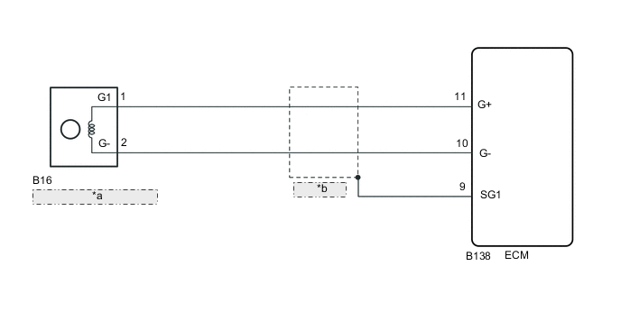
| *a | Camshaft Position Sensor |
| *b | (Shielded) |
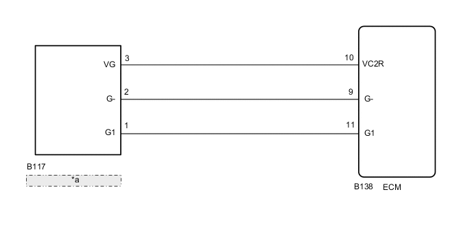
| *a | Camshaft Position Sensor |
CAUTION / NOTICE / HINT
Tech Tips
-
When the ECM must be replaced, before replacing the ECM, perform the "Learning Values Save" function using the GTS. Then after installing a new ECM, perform all of the initialization and registration procedures for the "Learning Values Write" function by following the instructions shown on the GTS display.
-
Read freeze frame data using the GTS. Freeze frame data records the engine condition when malfunctions are detected. When troubleshooting, freeze frame data can help determine if the vehicle was moving or stationary, if the engine was warmed up or not, and other data from the time the malfunction occurred.
PROCEDURE
-
SYSTEM CHECK
-
Check whether the vehicle is equipped with the stop and start system.
Result Result Proceed to The vehicle is not equipped with the stop and start system A The vehicle is equipped with the stop and start system B
B 
CHECK TERMINAL VOLTAGE (POWER SOURCE OF CAMSHAFT POSITION SENSOR) Click here
A 
-
-
INSPECT CAMSHAFT POSITION SENSOR
-
Inspect the camshaft position sensor.
Result Proceed to OK NG
NG
GO TO STEP 8 Click here
OK
-
-
CHECK HARNESS AND CONNECTOR (CAMSHAFT POSITION SENSOR - ECM)
-
Disconnect the camshaft position sensor connector.
-
Disconnect the ECM connector.
-
Measure the resistance according to the value(s) in the table below.
Standard Resistance Tester Connection Condition Specified Condition B16-1 (G1) - B138-11 (G+) Always Below 1 Ω B16-2 (G-) - B138-10 (G-) Always Below 1 Ω B16-1 (G1) or B138-11 (G+) - Body ground Always 10 kΩ or higher B16-2 (G-) or B138-10 (G-) - Body ground Always 10 kΩ or higher Result Proceed to OK NG
NG
REPAIR OR REPLACE HARNESS OR CONNECTOR Click here
OK
-
-
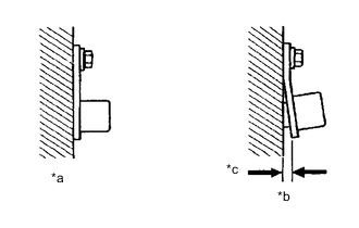
CHECK SENSOR INSTALLATION (CAMSHAFT POSITION SENSOR)
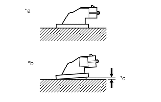
*a Normal *b Abnormal *c Clearance
-
Check the camshaft position sensor installation.
OK Sensor is installed correctly. Result Proceed to OK NG
NG
SECURELY REINSTALL SENSOR Click here
OK
-
-
CHECK CAMSHAFT (TIMING ROTOR)
-
Check the timing rotor of the camshaft.
OK Camshaft timing rotor does not have any cracks or deformation. Result Proceed to OK NG
NG
REPLACE CAMSHAFT Click here
OK
-
-
ADJUST VALVE TIMING
-
Adjust the valve timing.
Result Proceed to NEXT
NEXT
-
-
CHECK WHETHER DTC OUTPUT RECURS (DTC P0340 AND/OR P0344)
-
Connect the GTS to the DLC3.
-
Turn the ignition switch to ON and turn the GTS on.
-
Clear the DTCs.
Powertrain > Engine and ECT > Clear DTCs -
Start the engine.
-
Enter the following menus: Powertrain / Engine and ECT / Trouble Codes.
-
Read the DTCs.
Powertrain > Engine and ECT > Trouble CodesResult Result Proceed to DTC P0340 and/or P0344 is output A DTC is not output B
B 
END
A
-
-
REPLACE CAMSHAFT POSITION SENSOR
-
Replace the camshaft position sensor.
Result Proceed to NEXT
NEXT
-
-
CHECK WHETHER DTC OUTPUT RECURS (DTC P0340 AND/OR P0344)
-
Connect the GTS to the DLC3.
-
Turn the ignition switch to ON and turn the GTS on.
-
Clear the DTCs.
Powertrain > Engine and ECT > Clear DTCs -
Start the engine.
-
Enter the following menus: Powertrain / Engine and ECT / Trouble Codes.
-
Read the DTCs.
Powertrain > Engine and ECT > Trouble CodesResult Result Proceed to DTC P0340 and/or P0344 is output A DTC is not output B
B
END
A
-
-
REPLACE ECM
-
Replace the ECM.
Result Proceed to NEXT
NEXT
-
-
CONFIRM WHETHER MALFUNCTION HAS BEEN SUCCESSFULLY REPAIRED
-
Connect the GTS to the DLC3.
-
Turn the ignition switch to ON and turn the GTS on.
-
Clear the DTCs.
Powertrain > Engine and ECT > Clear DTCs -
Start the engine.
-
Enter the following menus: Powertrain / Engine and ECT / Trouble Codes.
-
Confirm that the DTC is not output again.
Powertrain > Engine and ECT > Trouble CodesResult Proceed to NEXT
NEXT
END
-
-
REPLACE CAMSHAFT
-
Replace the camshaft.
Result Proceed to NEXT
NEXT
GO TO STEP 9 Click here
-
-
SECURELY REINSTALL SENSOR
-
Securely reinstall the camshaft position sensor.
Result Proceed to NEXT
NEXT
GO TO STEP 9 Click here
-
-
REPAIR OR REPLACE HARNESS OR CONNECTOR
Result Proceed to NEXT
NEXT
GO TO STEP 9 Click here
-
CHECK TERMINAL VOLTAGE (POWER SOURCE OF CAMSHAFT POSITION SENSOR)
-
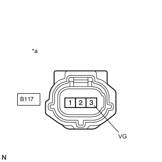
*a Front view of wire harness connector
(to Camshaft Position Sensor)
Disconnect the camshaft position sensor connector.
-
Turn the ignition switch to ON.
-
Measure the voltage according to the value(s) in the table below.
Standard Voltage Tester Connection Condition Specified Condition B117-3 (VG) - Body ground Ignition switch ON 4.5 to 5.5 V Result Proceed to OK NG
NG
CHECK HARNESS AND CONNECTOR (CAMSHAFT POSITION SENSOR - ECM) Click here
OK
-
-
CHECK HARNESS AND CONNECTOR (CAMSHAFT POSITION SENSOR - ECM)
-
Disconnect the camshaft position sensor connector.
-
Disconnect the ECM connector.
-
Measure the resistance according to the value(s) in the table below.
Standard Resistance Tester Connection Condition Specified Condition B117-2 (G-) - B138-9 (G-) Always Below 1 Ω B117-1 (G1) - B138-11 (G1) Always Below 1 Ω B117-2 (G-) or B138-9 (G-) - Body ground Always 10 kΩ or higher B117-1 (G1) or B138-11 (G1) - Body ground Always 10 kΩ or higher Result Proceed to OK NG
NG
REPAIR OR REPLACE HARNESS OR CONNECTOR Click here
OK
-
-
CHECK SENSOR INSTALLATION (CAMSHAFT POSITION SENSOR)
-
*a Normal *b Abnormal *c Clearance Check the camshaft position sensor installation.
OK Sensor is installed correctly. Result Proceed to OK NG
NG
SECURELY REINSTALL SENSOR Click here
OK
-
-
CHECK NO. 2 CRANK ANGLE SENSOR PLATE (TIMING ROTOR)
-
Check the NO. 2 crank angle sensor plate.
OK Sensor plate does not have any cracks or deformation. Result Proceed to OK NG
NG
REPLACE NO. 2 CRANK ANGLE SENSOR PLATE Click here
OK
-
-
REPLACE CAMSHAFT POSITION SENSOR
-
Replace the camshaft position sensor.
Result Proceed to NEXT
NEXT
-
-
CHECK WHETHER DTC OUTPUT RECURS (DTC P0340 AND/OR P0344)
-
Connect the GTS to the DLC3.
-
Turn the ignition switch to ON and turn the GTS on.
-
Clear the DTCs.
Powertrain > Engine and ECT > Clear DTCs -
Start the engine.
-
Enter the following menus: Powertrain / Engine and ECT / Trouble Codes.
-
Read the DTCs.
Powertrain > Engine and ECT > Trouble CodesResult Result Proceed to DTC P0340 and/or P0344 is output A DTC is not output B
B
END
A
-
-
ADJUST VALVE TIMING
-
Adjust the valve timing.
Result Proceed to NEXT
NEXT
GO TO STEP 9 Click here
-
-
REPLACE NO. 2 CRANK ANGLE SENSOR PLATE
-
Replace the NO. 2 crank angle sensor plate.
Result Proceed to NEXT
NEXT
GO TO STEP 9 Click here
-
-
SECURELY REINSTALL SENSOR
-
Securely reinstall the camshaft position sensor.
Result Proceed to NEXT
NEXT
GO TO STEP 9 Click here
-
-
REPAIR OR REPLACE HARNESS OR CONNECTOR
Result Proceed to NEXT
NEXT
GO TO STEP 9 Click here
-
CHECK HARNESS AND CONNECTOR (CAMSHAFT POSITION SENSOR - ECM)
-
Disconnect the camshaft position sensor connector.
-
Disconnect the ECM connector.
-
Measure the resistance according to the value(s) in the table below.
Standard Resistance Tester Connection Condition Specified Condition B117-3 (VG) - B138-10 (VC2R) Always Below 1 Ω B117-3 (VG) or B138-10 (VC2R) - Body ground Always 10 kΩ or higher Result Proceed to OK NG
OK
GO TO STEP 9 Click here
NG
GO TO STEP 24 Click here
-