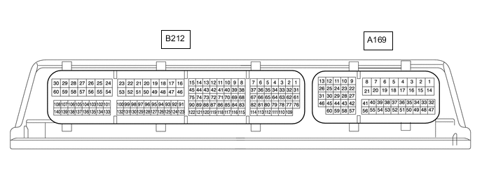
ECD SYSTEM(w/ Glow Plug Controller) TERMINALS OF ECM
Tech Tips
The standard voltage between each pair of ECM terminals is shown in the table below. The appropriate conditions for checking each pair of terminals are also indicated.
The result of the checks should be compared with the standard voltage for that pair of terminals, which is displayed in the Specified Condition column.
The illustration above can be used as a reference to identify the ECM terminal locations.
| Terminal No. (Symbol) | Wiring Color | Terminal Description | Condition | Specified Condition |
|---|---|---|---|---|
| B212-16 (HAF2) - A169-5 (E2) | Y - W-B | Air fuel ratio sensor heater (for sensor 2) |
Ignition switch ON | 11 to 14 V |
| Idling | Pulse generation (See waveform 1) |
|||
| B212-18 (VNM-) - A169-4 (E1) | W*3 - W-B V*4 - W-B |
VN turbocharger motor | Idling with warm engine | Pulse generation |
| B212-20 (M-) - A169-4 (E1) | G*3 - W-B L*4 - W-B |
Diesel throttle duty signal | Engine racing | Pulse generation |
| B212-21 (EGM-) - A169-4 (E1) | B - W-B | EGR valve motor | Idling with warm engine | Pulse generation |
| B212-24 (IJ4+) - B212-54 (IJ4-) | L - R-L | Injector | Idling | Pulse generation |
| B212-25 (IJ3+) - B212-55 (IJ3-) | W - R-B | Injector | Idling | Pulse generation |
| B212-26 (IJ2+) - B212-56 (IJ2-) | R - W | Injector | Idling | Pulse generation |
| B212-27 (IJ1+) - B212-57 (IJ1-) | W - B | Injector | Idling | Pulse generation |
| B212-28 (V20) - A169-4 (E1) | R - W-B | Oil pressure switching valve assembly | Oil pressure switching valve ON | 0 to 1.5 V |
| Oil pressure switching valve OFF | 11 to 14 V | |||
| B212-30 (PCV) - A169-4 (E1) | L - W-B | Supply pump (suction control valve) | Idling | Pulse generation (See waveform 2) |
| B212-46 (HAF1) - A169-5 (E2) | L - W-B | Air fuel ratio sensor heater (for sensor 1) |
Ignition switch ON | 11 to 14 V |
| Idling | Pulse generation (See waveform 1) |
|||
| B212-48 (VNM+) - A169-4 (E1) | R*3 - W-B P*4 - W-B |
VN turbocharger motor | Idling with warm engine | Pulse generation |
| B212-50 (M+) - A169-4 (E1) | Y*3 - W-B G*4 - W-B |
Diesel throttle duty signal | Engine racing | Pulse generation |
| B212-51(EGM+) - A169-4 (E1) | W - W-B | EGR valve motor | Idling with warm engine | Pulse generation |
| B212-58 (ECBV) - A169-4 (E1) | G - W-B | VSV for EGR cooler bypass valve | Ignition switch ON with cold engine | 0 to 1.5 V |
| Idling with warm engine | 11 to 14 V | |||
| B212-60 (PRV) - A169-4 (E1) | W - W-B | Pressure control valve signal | Drive vehicle at 50 km/h (31 mph) in third gear, and then decelerate by releasing accelerator pedal | Pulse generation (See waveform 3) |
| B212-63 (VPIM) - B212-110 (EPIM) | R - Y | Power source of diesel turbo pressure sensor | Ignition switch ON | 4.75 to 5.25 V |
| B212-64 (VCEG) - B212-111 (EEGL) | W - B | Power source of EGR valve position sensor | Ignition switch ON | 4.5 to 5.5 V |
| B212-65 (VCTA) - B212-112 (ETA) | V - P | Power source of diesel throttle position sensor | Ignition switch ON | 4.5 to 5.5 V |
| B212-67 (VNVC) - B212-114 (VNE2) | W - B | Power source of nozzle vane position sensor | Ignition switch ON | 4.5 to 5.5 V |
| B212-68 (VCG) - A169-4 (E1) | R - W-B | Power source of camshaft position sensor | Ignition switch ON | 4.5 to 5.5 V |
| B212-70 (VCS) - B212-117 (E2S) | R - G | Power source of fuel pressure sensor | Ignition switch ON | 4.5 to 5.5 V |
| B212-71 (VCPX) - B212-118 (EPEX) | R - G | Power source of differential pressure sensor | Ignition switch ON | 4.75 to 5.25 V |
| B212-76 (RE2) - A169-4 (E1) | P - W-B | Air fuel ratio sensor signal (for sensor 2) |
Ignition switch ON | 2.1 to 3.5 V |
| B212-77 (AF2-) - A169-4 (E1) | L - W-B | Air fuel ratio sensor signal (for sensor 2) |
Ignition switch ON | 2.35 to 2.65 V |
| B212-78 (PIM) - B212-110 (EPIM) | G - Y | Diesel turbo pressure sensor | Ignition switch ON(same as atmosphere pressure) | 0.8 to 1.4 V |
| B212-79 (EGLS) - B212-111 (EEGL) | G - B | EGR valve position sensor | EGR valve fully closed | 0.8 to 1.6 V |
| EGR valve fully opened | 3.6 to 4.4 V | |||
| B212-80 (VTA1) - B212-112 (ETA) | LG - P | Diesel throttle position sensor | Throttle valve fully opened | 3.2 to 4.9 V |
| Throttle valve fully closed | 0.5 to 1.1 V | |||
| B212-82 (VTAI) - B212-114 (VNE2) | R - B | Nozzle vane position sensor | VN turbocharger fully closed | 0.9 to 2.1 V |
| VN turbocharger fully opened | 3.0 to 4.1 V | |||
| B212-83 (G+) - B212-115 (G-) | L - G | Camshaft position sensor | Idling | Pulse generation (See waveform 4) |
| B212-85 (PC) - B212-117 (E2S) | W - G | Fuel pressure sensor (common rail pressure sensor) | Idling | 1.0 to 1.3 V |
| B212-86 (PEX) - B212-118 (EPEX) | P - G | Differential pressure sensor | Ignition switch ON | 0.5 to 1.0 V |
| B212-90 (SNE) - Body ground | BR - - | Shielded earth (ground) circuit of crankshaft position sensor | Always | Below 1 Ω |
| B212-92 (THCO) - B212-93 (ETCO) | B - V | Exhaust gas temperature sensor B1S2 | Idling with warm engine | 2.9 to 3.3 V |
| B212-96 (THA) - B212-100 (EVG) | LG*3 - BR L*4 - BR |
Intake air temperature sensor | Idling, intake air temperature 0 to 80 °C (32 to 176°F) | 0.5 to 3.4 V |
| B212-97 (VG) - B212-100 (EVG) | P*3 - BR LG*4 - BR |
Mass air flow meter | Idling | Pulse generation (See waveform 5) |
| B212-98 (OILH) - A169-4 (E1) | R - W-B | Engine oil level upper switch | Oil level upper switch off | 4.5 to 5.0 V |
| Oil level upper switch ON | 0 to 1.5 V | |||
| B212-99 (VCVG) - B212-100 (EVG) | L*3 - BR P*4 - BR |
Power source of mass air flow meter (for VG) | Ignition switch ON | 4.5 to 5.5 V |
| B212-101 (THF) - B212-133 (ETHF) | GR - BR | Fuel temperature sensor | Idling | 0.5 to 2.0 V |
| B212-103 (THW) - B212-135 (ETHW) | B - BR | Engine coolant temperature sensor | Idling, engine coolant temperature 80°C (176°F) | 0.2 to 1.0 V |
| B212-109 (AF2+) - A169-4 (E1) | R - W-B | Air fuel ratio sensor signal (for sensor 2) |
Ignition switch ON | 1.5 to 4.9 V |
| B212-121 (NE+) - B212-122 (NE-) | R - G | Crankshaft position sensor | Idling | Pulse generation (See waveform 6) |
| B212-123 (THIA) - B212-91 (ETHI) | V - GR | Intake air temperature sensor (intake manifold) | Idling, intake air temperature 0 to 80 °C (32 to 176°F) | 0.5 to 2.0 V |
| B212-124 (THCI) - B212-125 (ETCI) | LG - L | Exhaust gas temperature sensor B1S1 | Idling with warm engine | 2.9 to 3.3 V |
| B212-127 (AF1+) - A169-4 (E1) | B - W-B | Air fuel ratio sensor signal (for sensor 1) |
Ignition switch ON | 1.5 to 4.9 V |
| B212-128 (RE1) - A169-4 (E1) | P - W-B | Air fuel ratio sensor signal (for sensor 1) |
Ignition switch ON | 2.1 to 3.5 V |
| B212-129 (AF1-) - A169-4 (E1) | L - W-B | Air fuel ratio sensor signal (for sensor 1) |
Ignition switch ON | 2.35 to 2.65 V |
| B212-131 (POP) - B212-130 (EPOP) | G - W | Oil pressure sender gauge assembly | Engine running | 0.38 to 4.66 V |
| B212-132 (VPOP) - B212-130 (EPOP) | B - W | Power source of oil pressure sender gauge assembly | Ignition switch ON | 4.75 to 5.25 V |
| A169-1 (+B3) - A169-4 (E1) | B*3 - W-B GR*4 - W-B |
Power source of ECM | Ignition switch ON | 11 to 14 V |
| A169-2 (+B) - A169-4 (E1) | B - W-B | Power source of ECM | Ignition switch ON | 11 to 14 V |
| A169-4 (E1) - Body ground | W-B - - | Ground | Always | Below 1 Ω |
| A169-5 (E2) - Body ground | W-B - - | Ground | Always | Below 1 Ω |
| A169-6 (NEO) - A169-4 (E1) | L - W-B | Engine speed | Idling | Pulse generation (See waveform 7) |
| A169-7 (RFC) - A169-4 (E1) | R - W-B | Cooling fan control | Ignition switch ON, A/C switch on (Max cool) | Pulse generation (See waveform 8) |
| A169-9 (MREL) - A169-4 (E1) | B - W-B | EFI-MAIN relay | Ignition switch ON | 11 to 14 V |
| 20 seconds elapsed since ignition switch off | 0 to 1.5 V | |||
| A169-10 (W) - A169-4 (E1) | LG - W-B | MIL | MIL illuminated | 0 to 3 V |
| MIL not illuminated | 11 to 14 V | |||
| A169-14 (+B2) - A169-4 (E1) | B*3 - W-B R*4 - W-B |
Power source of ECM | Ignition switch ON | 11 to 14 V |
| A169-15 (BATT) - A169-4 (E1) | W - W-B | Battery (for measuring the battery voltage and for the ECM memory) | Always | 11 to 14 V |
| A169-17 (E3) - Body ground | W-B - - | Ground | Always | Below 1 Ω |
| A169-18 (E4) - Body ground | W-B - - | Ground | Always | Below 1 Ω |
| A169-19 (TACH) - A169-4 (E1) | GR - W-B | Engine speed | Idling | Pulse generation |
| A169-20 (GREL) - A169-4 (E1) | L - W-B | Glow plug relay assembly | Ignition switch ON | 11 to 14 V |
| A169-24 (GLDO) - A169-4 (E1) | R - W-B | Glow plug controller | Glow plug on | Pulse generation |
| A169-25 (CANL) - A169-4 (E1) | W - W-B | CAN communication line | Ignition switch ON | Pulse generation (See waveform 9) |
| A169-26 (CANH) - A169-4 (E1) | B - W-B | CAN communication line | Ignition switch ON | Pulse generation (See waveform 10) |
| A169-27 (VCPA) - A169-22 (EPA) | B*1*3 - Y*1*3 B*4 - Y*4 P*2*3 - V*2*3 |
Power source of accelerator pedal position sensor (for VPA) | Ignition switch ON | 4.5 to 5.5 V |
| A169-28 (VCP2) - A169-23 (EPA2) | L - P*1 L - G*2*3 L - Y*2*4 |
Power source of accelerator pedal position sensor (for VPA2) | Ignition switch ON | 4.5 to 5.5 V |
| A169-30 (CANP) - A169-4 (E1) | B - W-B | CAN communication line | Ignition switch ON | Pulse generation (See waveform 10) |
| A169-31 (CANN) - A169-4 (E1) | SB - W-B | CAN communication line | Ignition switch ON | Pulse generation (See waveform 9) |
| A169-32 (MHSW)*5 - A169-4 (E1) | R - W-B | Power heater switch signal | Power heater switch ON | 11 to 14 V |
| A169-33 (ELS) - A169-4 (E1) | V - W-B | Tail Light signal | Tail light ON | 11 to 14 V |
| Tail light off | 0 to 1.5 V | |||
| A169-35 (GLDI) - A169-4 (E1) | V - W-B | Glow plug controller | Glow plug on | Pulse generation |
| A169-36 (D) - A169-4 (E1) | GR - W-B | No. 2 clutch pedal switch assembly | Ignition switch ON, clutch pedal released | 11 to 14 V |
| Ignition switch ON, clutch pedal depressed | 0 to 1.5 V | |||
| A169-37 (IGSW) - A169-4 (E1) | B - W-B | Ignition switch | Ignition switch ON | 11 to 14 V |
| A169-38 (ST1-) - A169-4 (E1) | R - W-B | Stop light switch (opposite to STP) |
Brake pedal depressed | 0 to 1.5 V |
| Brake pedal released | 7.5 to 14 V | |||
| A169-42 (VPA) - A169-22 (EPA) | W - Y*1*3 W - Y*4 W - V*2*3 |
Accelerator pedal position sensor (for engine control) | Ignition switch ON, accelerator pedal fully released | 0.5 to 1.1 V |
| Ignition switch ON, accelerator pedal fully depressed | 2.6 to 4.5 V | |||
| A169-43 (VPA2) - A169-23 (EPA2) | R - P*1 R - G*2*3 R - Y*2*4 |
Accelerator pedal position sensor (for sensor malfunction detection) | Ignition switch ON, accelerator pedal fully released | 1.2 to 2.0 V |
| Ignition switch ON, accelerator pedal fully depressed | 3.4 to 4.75 V | |||
| A169-48 (STP) - A169-4 (E1) | L - W-B | Stop light switch | Brake pedal depressed | 7.5 to 14 V |
| Brake pedal released | 0 to 1.5 V | |||
| A169-50 (TC) - A169-4 (E1) | P - W-B | Terminal TC of DLC3 | Ignition switch ON | 11 to 14 V |
| A169-51 (SPD) - A169-4 (E1) | V - W-B | Speed signal from combination meter | Ignition switch ON, driving wheel rotating slowly | Pulse generation (See waveform 11) |
| A169-52 (ELS2) - A169-4 (E1) | L - W-B | Electric load | Defogger switch ON | 7.5 to 14 V |
| Defogger switch off | 0 to 1.5 V | |||
| A169-53 (STA) - A169-4 (E1) | LG - W-B | Starter signal | Cranking | 6.0 V or higher |
| A169-54 (R) - A169-4 (E1) | R - W-B | Back-up light switch signal | Back-up light switch ON | 11 to 14 V |
-
*1: for LHD
*2: for RHD
*3: for Hatchback, Wagon
*4: for Sedan
*5: w/ Combustion type power heater
-
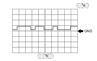
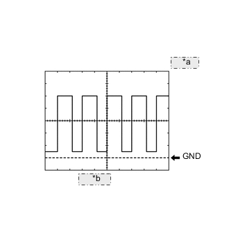
Waveform 1
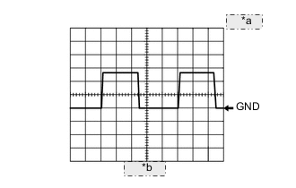
*a 5 V/DIV *b 2 ms/DIV Air Fuel Ratio Sensor Heater Signal ECM Terminal Name HAF1 and E2
HAF2 and E2
Tester Range 5 V/DIV, 2 ms/DIV Condition Idling Tech Tips
The wavelength varies depending on the engine operating conditions.
-
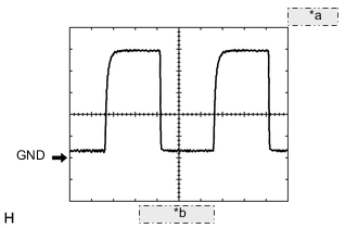
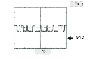
Waveform 2
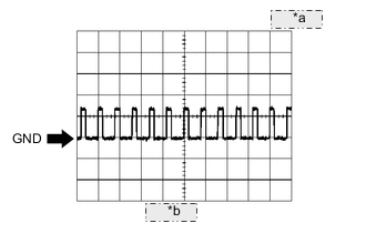
*a 10 V/DIV *b 5 ms/DIV Suction Control Valve Signal ECM Terminal Name PCV and E1 Tester Range 10 V/DIV, 5 ms/DIV Condition Idling Tech Tips
The waveform varies depending on the suction control valve operation.
-
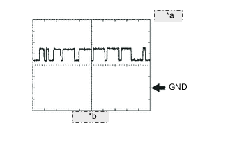
Waveform 3
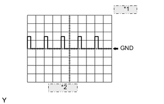
*1 10 V/DIV *2 0.5 ms/DIV Pressure Control Valve Signal ECM Terminal Name PRV and E1 Tester Range 10 V/DIV, 0.5 ms/DIV Condition Drive vehicle at 50 km/h (31 mph) in third gear, and then decelerate by releasing accelerator pedal Tech Tips
The waveform varies depending on the pressure control valve operation.
-
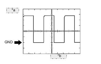
Waveform 4
*a 5 V/DIV *b 20 ms/DIV Camshaft Position Sensor Signal ECM Terminal Name G+ and G- Tester Range 5 V/DIV, 20 ms/DIV Condition Idling Tech Tips
The waveform varies depending on the engine speed.
-
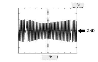
WAVEFORM 5
*a 1 V/DIV. *b 100 μs./DIV. Mass Air Flow Meter Signal ECM Terminal Name Between VG and EVG Tester Range 1 V/DIV., 100 μs./DIV. Condition Idling -
Waveform 6
*a 5 V/DIV *b 10 ms/DIV Crankshaft Position Sensor Signal ECM Terminal Name NE+ and NE- Tester Range 5 V/DIV, 10 ms/DIV Condition Idling Tech Tips
The waveform varies depending on the engine speed.
-
Waveform 7
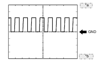
*a 5 V/DIV *b 1 ms/DIV Engine Speed Signal ECM Terminal Name NEO and E1 Tester Range 5 V/DIV, 1 ms/DIV Condition Idling Tech Tips
The waveform varies depending on the crankshaft position sensor signal.
-
Waveform 8
*a 1 V/DIV *b 4 ms/DIV Cooling Fan Control Signal ECM Terminal Name RFC and E1 Tester Range 1 V/DIV, 4 ms/DIV Condition Ignition switch ON, A/C switch on (Max cool) Tech Tips
The duty ratio varies depending on the engine coolant temperature.
-
Waveform 9
*a 1 V/DIV *b 10 μs/DIV CAN Communication Signal (Reference) ECM Terminal Name CANL and E1
CANN and E1
Tester Range 1 V/DIV, 10 μs/DIV Condition Ignition switch ON Tech Tips
The wavelength becomes shorter depending on the CAN communication signal.
-
Waveform 10
*a 1 V/DIV *b 10 μs/DIV CAN Communication Signal (Reference) ECM Terminal Name CANH and E1
CANP and E1
Tester Range 1 V/DIV, 10 μs/DIV Condition Ignition switch ON Tech Tips
The wavelength becomes shorter depending on the CAN communication signal.
-
Waveform 11
*a 1 V/DIV *b 10 ms/DIV Vehicle Speed Signal ECM Terminal Name SPD and E1 Tester Range 1 V/DIV, 10 ms/DIV Condition Ignition switch ON, driving wheel rotating slowly Tech Tips
The wavelength becomes shorter as the vehicle speed increases.