ECD SYSTEM(w/ Glow Plug Controller) SYSTEM DESCRIPTION
-
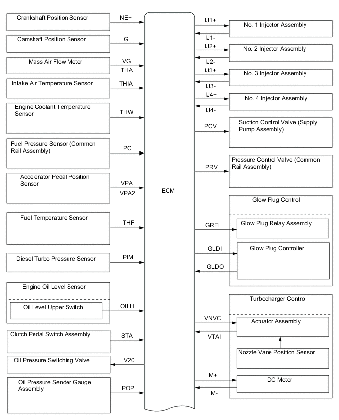
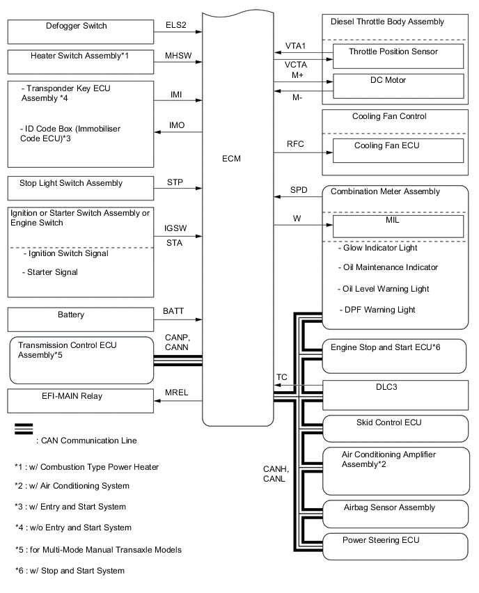
ENGINE CONTROL SYSTEM
-
System Control Table
-
The engine control system of the 1ND-TV engine uses the following controls.
Controls Description Fuel Injection Volume Control Based on the signals received from various sensors, the ECM determines the fuel injection volume in accordance with the engine condition. Fuel Injection Timing Control Based on the signals received from various sensors, the ECM determines the fuel injection timing in accordance with the engine condition. Fuel Pressure Control Based on the signals received from various sensors, the ECM determines the fuel pressure via the fuel metering unit and pressure control valve in accordance with the engine condition. Idle Speed Control The ECM determines the idle speed in accordance with the engine condition, and controls the fuel injection volume in order to maintain the target idle speed. Pilot Injection Control Based on the signals received from various sensors, the ECM determines pilot injection volume, timing, and interval (between pilot injection and main injection) in accordance with the engine condition. Glow Plug Control Controls the length of time current is applied to the glow plugs, in accordance with the engine coolant temperature. Turbocharger Control Based on signals from various sensors, the ECM controls the turbocharger in accordance with engine condition by adjusting the nozzle vane. Intake Throttle Control Based on the signals received from various sensors, the ECM determines throttle position in accordance with engine condition. Fully closes the diesel throttle control valve in order to reduce vibration when the engine is stopped.
-
-
Fuel Injection Volume Control
-
Fuel injection volume contorl has two values, "Final Injection Volume", "Starting Injection Volume".
Final Injection Volume The ECM compares the basic and maximum injection volumes, and determines the smaller calculated value to be the final injection volume. The ECM changes injection volume to ensure drivability when the clutch switch is ON (the clutch pedal is not depressed). Starting Injection Volume The starting injection volume is determined in accordance with the crankshaft position sensor signal (cranking time) and engine coolant temperature sensor signal. When the engine is cold, the engine coolant temperature will be lower and the injection volume will be greater. Basic Injection Volume:
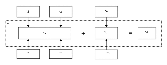
*1 ECM *2 Engine Coolant Temperature Sensor *3 Crankshaft Position Sensor (Engine Speed) *4 Clutch Pedal Switch Assembly *5 Accelerator Pedal Position Sensor - - *a Calculation of Basic Injection Volume *b Vehicle Speed Signal *c Basic Injection Volume Correction *d Basic Injection Volume *e ISC Correction - - Maximum Injection Volume:
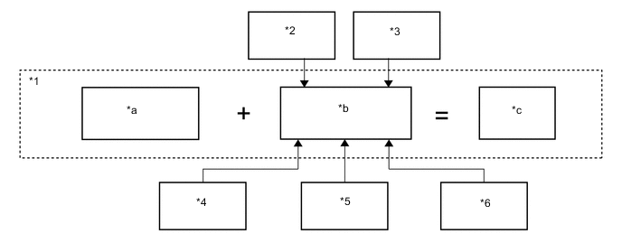
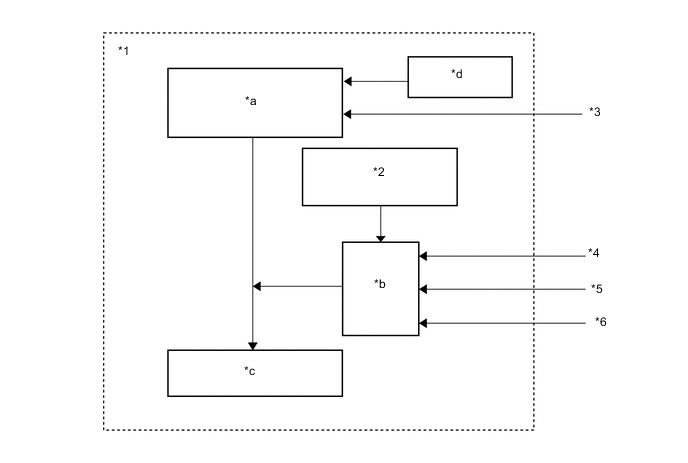
*1 ECM *2 Engine Coolant Temperature Sensor *3 Crankshaft Position Sensor (Engine Speed) *4 Diesel Turbo Pressure Sensor *5 Mass Air Flow Meter *6 Accelerator Pedal Position Sensor *a Basic/Maximum Injection Volume (Map data inside of ECM) *b Maximum Injection Volume Correction *c Maximum Injection Volume - - Final Injection Volume:
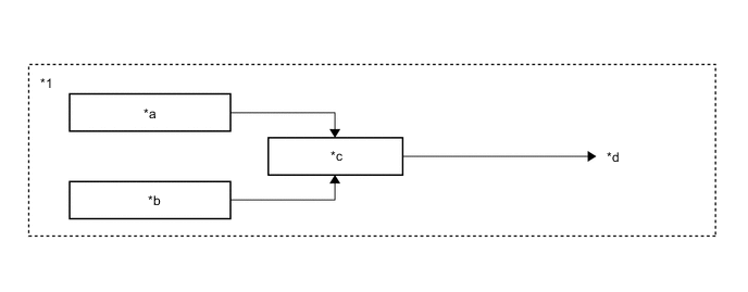
*1 ECM - - *a Basic Injection Volume *b Maximum Injection Volume *c Comparison
(Selects lower injection volume)
*d Final Injection Volume
-
-
Fuel Injection Timing Control
-
Fuel injection timing is controlled as shown below.
*1 ECM *2 Atmospheric Pressure Sensor *3 Crankshaft Position Sensor (Engine Speed) *4 Intake Air Temperature Sensor *5 Engine Coolant Temperature Sensor *6 Diesel Turbo Pressure Sensor *a Basic Injection Timing *b Correction *c Injection Timing *d Final Injection Volume
-
-
Fuel Pressure Control
-
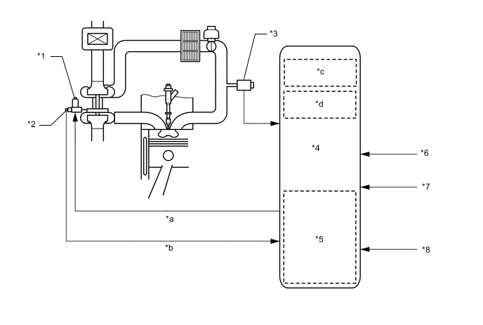
The ECM calculates the target injection pressure (30000 to 180000 kPa) based on the final injection volume and signals from the crankshaft position sensor.
-
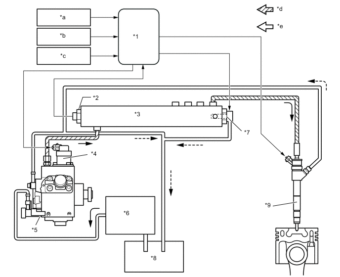
To control fuel pressure, signals sent to the fuel metering unit of the supply pump regulate the pumping volume. Signals sent to the pressure control valve of the common-rail regulate the discharge volume, so that the pressure detected by the fuel pressure sensor matches the target injection pressure.
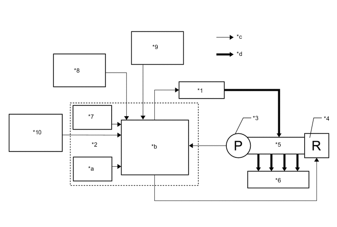
*1 Suction Control Valve (Supply Pump Assembly) *2 ECM *3 Fuel Pressure Sensor (Common Rail Assembly) *4 Pressure Control Valve (Common Rail Assembly) *5 Common Rail Assembly *6 Injector assembly *7 Atmospheric Pressure Sensor *8 Intake Air Temperature Sensor *9 Engine Coolant Temperature Sensor *10 Crankshaft Position Sensor (Engine Speed) *a Final Injection Volume *b Calculation of Target Injection Pressure *c Electric Signal *d Fuel Pressure Suction control valve control The ECM controls the suction control valve opening in order to regulate the fuel volume that is pumped by the supply pump to the common-rail. Consequently, the fuel pressure in the common-rail is controlled to the target injection pressure. Suction control valve opening small When the suction control valve opening is small, the fuel suction area is kept small, which decreases the transferable fuel quantity. The plunger strokes fully, however, the suction volume is small due to the small suction area. Pumping will start when the fuel pressure has becomes higher than the common-rail pressure. Suction control valve opening large When the suction control valve opening is large, the fuel suction area is kept large, which increases the transferable fuel quantity. The plunger strokes fully and suction volume will increase because the suction area is large. Pumping will start when the fuel pressure has becomes higher than the common-rail pressure. Suction Control Valve Opening Small:
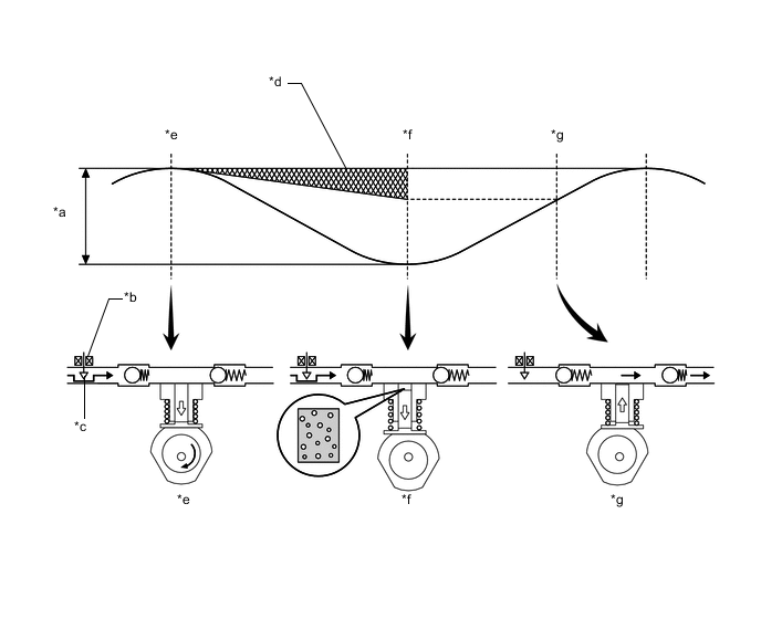
*a Cam Stroke *b Suction Control Valve *c Small Suction Area *d Fuel Pumping Mass *e Plunger Top-dead-center *f Plunger Bottom-dead-center *g Pumping Starting Point - - Suction Control Valve Opening Large:
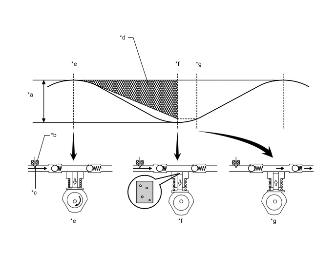
*a Cam Stroke *b Suction Control Valve *c Large Suction Area *d Fuel Pumping Mass *e Plunger Top-dead-center *f Plunger Bottom-dead-center *g Pumping Starting point - -
-
-
Idle Speed Control
-
ISC correction is controlled as shown below.
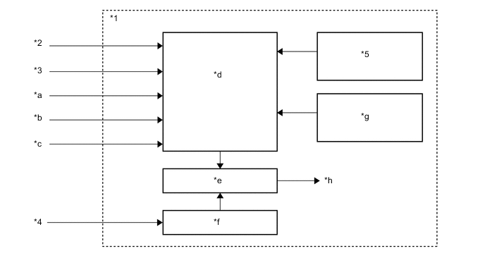
*1 ECM *2 Engine Coolant Temperature Sensor *3 Vehicle Speed Sensor *4 Crankshaft Position Sensor *5 Atmospheric Pressure Sensor - - *a A/C Switch Signal (w/ Air Conditioning System) *b Power Heater Signal (w/ Combustion Type Power Heater) *c PTC Heater Signal (w/ PTC Heater) *d Target Speed Calculation *e Comparison *f Actual Engine Speed *g DPF Status *h ISC Correction
-
-
Pilot Injection Control
-
Pilot injection is a method that provides an auxiliary fuel injection before the main fuel injection takes place. The purpose of pilot injection is to gently start the combustion of the fuel of the main injection in order to reduce combustion noise.
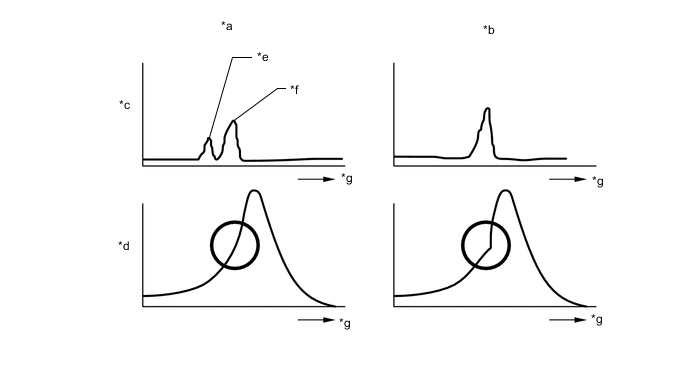
*a w/ Pilot Injection Control *b w/o Pilot Injection Control *c Fuel Injection *d Combustion Pressure *e Pilot Injection *f Main Injection *g Time - - -
During pilot injection, the pilot injection volume, timing, and interval (between pilot injection and main injection) are controlled as shown below.
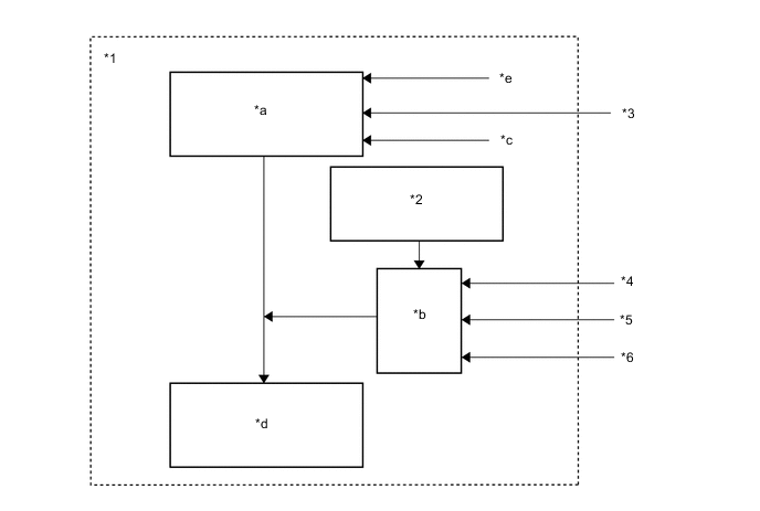
*1 ECM *2 Atmospheric Pressure Sensor *3 Crankshaft Position Sensor (Engine Speed) *4 Atmospheric Temperature Sensor *5 Engine Coolant Temperature Sensor *6 Diesel Turbo Pressure Sensor *a Basic Pilot Injection (Volume, Timing, Interval) *b Correction *c DPF Status *d Pilot Injection (Volume, Timing, Interval) *e Final Injection Volume - -
-
-
Turbocharger Control
-
The ECM controls the nozzle vane position in order to obtain the calculated target turbo pressure appropriate to the engine operating condition.
-
The ECM calculates the optimal nozzle vane position in accordance with the driving conditions (engine speed, injection volume, atmospheric pressure, engine coolant temperature, etc.). The ECM controls the nozzle vane position in accordance with the target nozzle vane position calculated by the ECM and the actual nozzle vane position signal provided by the nozzle vane position sensor.
*1 DC Motor *2 Nozzle Vane Position Sensor *3 Diesel Turbo Pressure Sensor *4 ECM *5 Atmospheric Pressure Sensor *6 Crankshaft Position Sensor *7 Engine Coolant Temperature Sensor *8 Atmospheric Temperature Sensor *a DC Motor Operation Current *b Actual Nozzle Vane Position Signal *c DPF Status *d Injection Volume
-
-
-
EMISSION CONTROL SYSTEM
-
System Control Table
-
The emission control system of the 1ND-TV engine has the following controls.
Control Description EGR Control Based on the signals received from the sensors, the ECM determines the EGR volume via the EGR valve and throttle valve in accordance with the engine condition. Catalyst Support Control Based on the signals received from the sensors, the ECM controls the fuel injection from the injector assembly and the intake air volume to purify NOx and PM. Air fuel Ratio Sensor Heater Control Maintains the temperature of the air fuel ratio sensors at an appropriate level to increase accuracy of detection of the oxygen concentration in the exhaust gas.
-
-
EGR Control
-
This system is designed to reduce and control NOx formation due to a reduction of peak temperature in the engine combustion chamber, which is accomplished by introducing exhaust gas into intake manifold.
-
By sensing the engine driving conditions and actual amount of EGR valve opening, the ECM operates the EGR valve and diesel throttle control motor, and regulates the amount of recirculated exhaust gas.
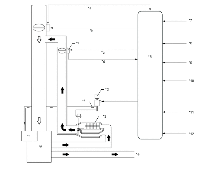
*1 Electric EGR Control Valve Assembly *2 VSV (for EGR Cooler Bypass Switching Valve) *3 EGR Cooler *4 Vacuum Pump *5 Engine *6 ECM *7 Accelerator Pedal Position Sensor *8 Crankshaft Position Sensor *9 Mass Air Flow Meter *10 Engine Coolant Temperature Sensor *11 Intake Air Temperature Sensor *12 Diesel Turbo Pressure Sensor *a Throttle Position Sensor Signal *b Throttle Valve Control *c EGR Valve Control *d EGR Valve Position Signal *e to Turbocharger *f Vacuum 
Exhaust Gas 
Intake Air
-
-
Catalyst Support Control
-
For effective functioning of the NOx-purifying NSR (NOx Storage Reduction) catalyst and PM-removing DPF, intake air volume and fuel injection pattern are controlled according to information from 2 exhaust temperature sensors, 2 air fuel ratio sensors and a differential pressure sensor.
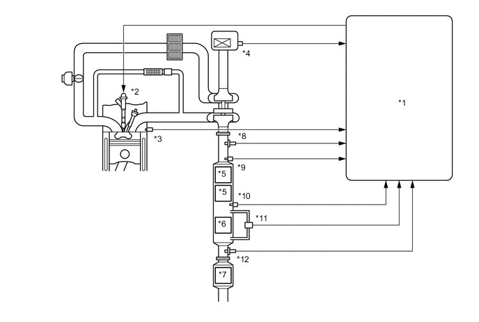
*1 ECM *2 Injector Assembly *3 Engine Coolant Temperature Sensor *4 Mass Air Flow Meter *5 NSR (NOx Storage Reduction) Catalyst *6 DPF (Diesel Particurate Filter) *7 H2S Sweeper *8 Air Fuel Ratio Sensor (Bank 1 Sensor 1) *9 Exhaust Gas Temperature Sensor B1S1 *10 Exhaust Gas Temperature Sensor B1S2 *11 Differential Pressure Sensor *12 Air Fuel Ratio Sensor (Bank 1 Sensor 2)
-
DPF Control
-
If the DPF catalyst temperature becomes low, catalyst performance decreases, resulting in an increase of the amount of Particulate Matter (PM) stuck in the filter substrate. When the ECM detects clogs in the filter substrate, by calculating the accumulated volume of PM discharged by the engine, after injection and idle-up control are performed to reduce PM. At the same time, the filter substrate temperature becomes high and the PM reacts with active oxygen and changes into CO2. Fuel efficiency drops during this control.
Tech Tips
In the after injection, fuel is injected into the cylinder at a timing at which the fuel is not combusted, sending the fuel into the DPF and increasing the exhaust gas temperature by catalytic oxidation reaction, resulting in increasing the catalyst temperature.
-
A small portion of the fuel injected by the after injection enters the crankcase via the cylinder walls, causing dilution of the engine oil. The oil level is less likely to increase during normal use, as the fuel in the oil evaporates with the increase in the engine oil temperature.
However, the engine oil is gradually diluted after consecutive driving of which the running distance per single trip is short, which results in reducing the lubricating performance. In an attempt to prevent this, the oil level sensor detects the engine oil level and turns on/blinks the oil maintenance indicator to urge the driver to change the engine oil.
-
NSR Control
-
The NSR catalyst adsorbs NOx, reducing the amount in the exhaust gas, but the amount that can be adsorbed is limited, so the NOx stored in the catalyst is periodically reduced. To reduce the NOx, the A/F of the exhaust gas passing through the catalyst must be controlled to a specified value to supply CO. For this reason, based on the information from the air fuel ratio sensor (bank 1 sensor 1), intake air volume and after injection are controlled to create a reducing atmosphere. Also, judgment of whether reduction has completed is made based on information from the air fuel ratio sensor (bank 1 sensor 2).
-
-
If the DPF catalyst temperature becomes low, catalyst performance decreases, resulting in an increase of the amount of Particulate Matter (PM) stuck in the filter substrate. When the ECM detects clogs in the filter substrate, by calculating the accumulated volume of PM discharged by the engine, after injection and idle-up control are performed to reduce PM. At the same time, the filter substrate temperature becomes high and the PM reacts with active oxygen and changes into CO2. Fuel efficiency drops during this control.
Tech Tips
In the after injection, fuel is injected into the cylinder at a timing at which the fuel is not combusted, sending the fuel into the DPF and increasing the exhaust gas temperature by catalytic oxidation reaction, resulting in increasing the catalyst temperature.
-
-
-
FUEL SYSTEM
-
Fuel System Description
-
A common-rail system manufactured by BOSCH is used in the fuel injection system. In this system, the highly pressurized fuel that is supplied by the supply pump is stored in the common rail, and ECM sends signals to the injector assemblies in order to control the injection timing and injection volume.
-
Quick disconnects are used to connect the fuel pipe with the fuel hose for excellent serviceability.
-
A fuel filter with a fuel heater is used.
*1 ECM *2 Fuel Pressure Sensor (Common Rail Assembly) *3 Common Rail Assembly *4 Suction Control Valve *5 Supply Pump Assembly *6 Fuel Filter with Heater *7 Pressure Control Valve (Common Rail Assembly) *8 Fuel Tank *9 Injector Assembly - - *a NE Signal *b G Signal *c Various Signal *d High Pressure Fuel *e Low Pressure Fuel - -
-
-
Supply Pump
-
Due to the rotation of the inner cam (eccentric cam), the outer cam pushes plunger "A" upward as illustrated below. The force of the spring pulls plunger "C". As a result, plunger "C" draws fuel in, and plunger "A" pumps fuel at the same time.
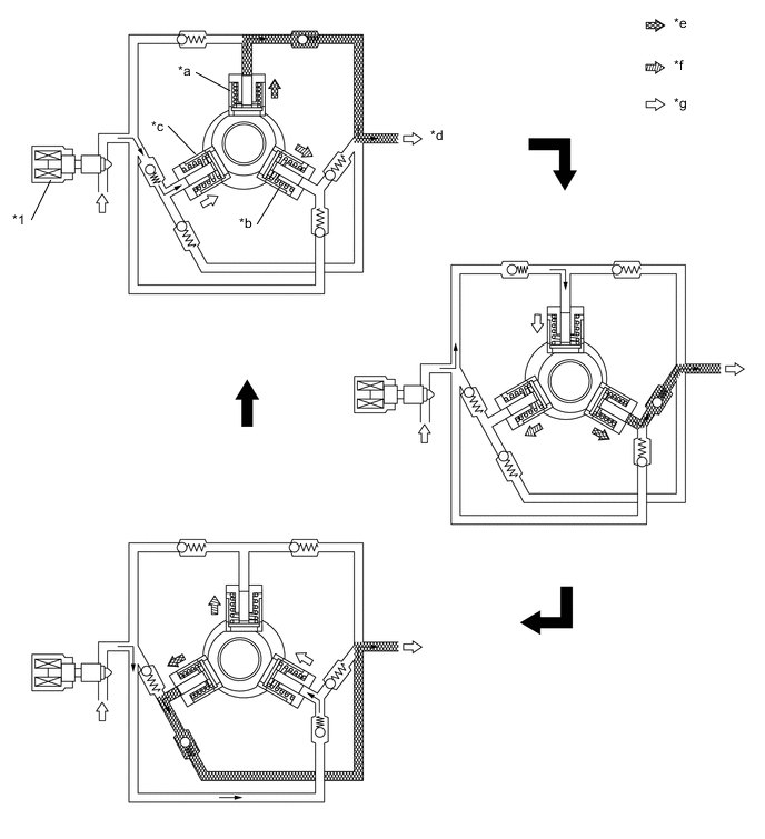
*1 Suction Control Valve - - *a Plunger A *b Plunger B *c Plunger C *d to Common-rail *e Pumping Complete *f Pumping Start *g Suction - -
-
-
Injector Assembly: Needle Opening (During Injection)
-
The actuator is activated
-
Valve bolt opens (moves downward) due to actuator lift
-
Pressure of nozzle needle tip decreases
-
Nozzle needle opens (moves upward)
-
-
Injector Assembly: Needle Closing (While Stopped)
-
The actuator is deactivated
-
Valve bolt closes (moves upward) due to the valve spring
-
Pressure of nozzle needle tip increases
-
Nozzle needle closes (moves downward)
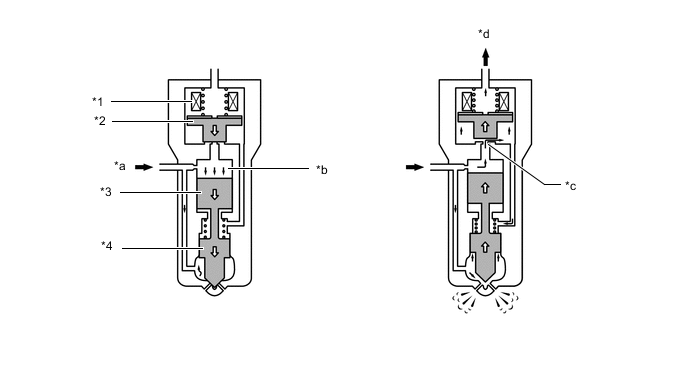
*1 Solenoid Coil *2 Solenoid Valve *3 Piston *4 Nozzle Needle *a Fuel (from Common Rail Assembly) *b Control Chamber *c Orifice *d Fuel (Return)
-
-