ECD SYSTEM(w/ Glow Plug Controller) PRECAUTION
-
INITIALIZATION AND REGISTRATION
Note
-
When the ECM and/or the other component(s) mentioned below are replaced, perform the following utility items on the GTS, referring to the corresponding Initialization and Registration procedure.
-
If the ECM is replaced, register the ECU communication ID for Engine Immobiliser System (w/o entry and stat system) (Refer to the Service Bulletin for Registration).
-
When the cable is disconnected from the negative (-) battery terminal, initialize the following system(s) after the cable is reconnected.
System Name See Procedure Stop and Start System Simple Intelligent Parking Assist System Power Door Lock Control System (for Hatchback, Wagon)
Tech Tips
When the ECM and other component(s) are replaced at the same time, perform the following utility items by following the instructions shown on the GTS display, starting with the ECM.
Replacement Part Utility Item See page ECM
-
Learning Values Save
-
Learning Values Write
-
VIN Registration or Frame Number Registration
Injector Assembly
-
Injector Compensation
-
Pilot Quantity Learning Values Reset
DPF Catalyst DPF Deterioration Record Clear Air Fuel Ratio Sensor A/F Sensor Compensation Reset Engine Assembly
-
Injector Compensation
-
Pilot Quantity Learning Values Reset
-
DPF Deterioration Record is the ash accumulation volume in the DPF catalytic converter calculated by the ECM. If the ash accumulation volume in the DPF catalytic converter increases, the difference in pressure in front of and behind the DPF catalytic converter will increase. The difference in pressure in front of and behind the DPF catalytic converter is offset depending on the volume of accumulated ash.
Tech Tips
-
Before replacing the ECM, perform the "Learning Values Save" function using the GTS. Then after installing the new ECM, perform all initialization and registration procedures for the "Learning Values Write" function by following the instructions shown on the GTS display.
-
After replacing any of the injector assemblies, perform both the "Injector Compensation" and the "Pilot Quantity Learning Values Reset" functions using the GTS.
-
After replacing the engine assembly, perform both the "Injector Compensation" and the "Pilot Quantity Learning Values Reset" functions using the GTS.
-
-
INJECTOR COMPENSATION CODE
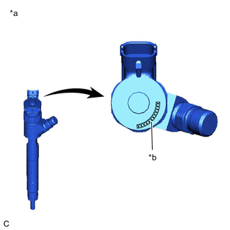
*a Example *b Injector Compensation Code Tech Tips
Each injector assembly has different fuel injection characteristics. In order to optimize the fuel injections, the ECM uses injector compensation codes to balance the different characteristics of each injector assembly. Injector compensation codes are 12-digit, alphanumeric values printed on the head of each injector.
Note
If an incorrect injector compensation code is input into the ECM, the engine assembly may rattle or engine idling may become rough. In addition, engine failure may occur and the life of the engine may be shortened.
-
ENGINE OIL CHANGE REMINDER LIGHT (MESSAGE) AND MIL
Tech Tips
Depending on the combination of output DTCs and the status of the engine oil change reminder light*1 or engine oil change reminder message*2*3 displayed and illumination condition of the MIL, the necessary procedures to be performed will vary. Therefore refer to the following table before bigining work.
*1: w/ Multi-information Display (Segment LCD Type).
*2: w/ Multi-information Display (Dot LCD Type).
*3: w/ Multi-information Display (Color Type).
-
Connect the GTS to the DLC3.
-
Turn the ignition switch to ON and turn the GTS on.
-
Enter the following menus: Powertrain / Engine and ECT / Trouble Codes.
-
Read the output DTCs.
-
Determine the necessary procedures according to the table below.
No. Engine Oil Change Reminder Light (Message) Status MIL Status Note Proceed to Engine Oil Change Reminder Light*1 Engine Oil Change Reminder Message*2*3 0 OFF OFF OFF Normal condition - 1 Blinks "OIL MAINTENANCE REQUIRED SOON"*2 or "Oil Maintenance required soon."*3 is displayed OFF
-
(a) Travel distance oil change request
-
(b) Cumulative soot oil change request
-
(c) Oil high level malfunction detected in 2 consecutive trips
-
Replace engine oil and filter
-
Reset oil maintenance light
-
Drive vehicle to reset oil high level malfunction
2 ON "OIL MAINTENANCE REQUIRED"*2 or "Oil Maintenance required."*3 is displayed OFF The engine oil reminder light turns on or a message is displayed when the vehicle is driven without replacing the engine oil after condition (a) or (b) above was detected. 3 ON "OIL MAINTENANCE REQUIRED"*2 or "Oil Maintenance required."*3 is displayed OFF
DTC P252F output
DTC P252F is stored when an oil high level malfunction is detected in 2 consecutive trips P252F
4 ON "OIL MAINTENANCE REQUIRED"*2 or "Oil Maintenance required."*3 is displayed ON
DTC P252F and P2463 output
-
The engine oil reminder light turns on*1 or a message is displayed*2*3 after the vehicle has been driven 400 km (249 miles) since DTC P252F was stored.
-
DTC P2463 is stored when the vehicle has benn driven 500 to 1000 km (311 to 621 miles)*4 since the engine oil reminder light turned on*1 or a message was displayed*2*3.
P252F
*1: w/ Multi-information Display (Segment LCD Type).
*2: w/ Multi-information Display (Dot LCD Type).
*3: w/ Multi-information Display (Color Type).
Tech Tips
*4: The distance the vehicle needs to be driven before DTC P2463 is stored varies depending on the operation conditions.
-
-
-
DPF WARNING LIGHT (MESSAGE)
-
If the DPF warning light*1 or DPF warning message*2 does not turn off a few seconds after the ignition switch is turned to ON, or if the DPF warning light turns on*1 or a DPF warning message is displayed*2 at any other time, perform the following procedure.
-
Drive the vehicle for 20 to 30 minutes at 65 km/h (40 mph) or more until the DPF warning light*1 or DPF warning message*2 turns off.
CAUTION:
When performing a drive test, obey all speed limits and traffic laws.
-
If the DPF warning light*1 or DPF warning message*2 does not turn off after 35 minutes or more, perform the following procedure.
(a) Connect the GTS to the DLC3. [A]
(b) Start the engine and turn the GTS on. [B]
(c) Clear the DTCs. [C]
(d) Enter the following menus: Powertrain / Engine and ECT / Active Test / Activate the DPF Rejuvenate (PM) / Data List / Exhaust Temperature B1S1, Exhaust Temperature B1S2, DPNR/DPF Status Reju(PM). [D]
Tech Tips
After clearing the DTCs, immediately perform the Active Test and drive the vehicle.
(e) According to the display on the GTS, perform the Active Test and drive the vehicle at a constant speed between 65 and 100 km/h (40 and 62 mph) while maintaining a constant engine speed of 2000 rpm or more (3rd gear). [E]
Note
When performing a drive test, obey all speed limits and traffic laws.
Tech Tips
While performing the Active Test, the accelerator pedal opening angle should be kept as constant as possible.
(f) Check that the values both Exhaust Temperature B1S1 and Exhaust Temperature B1S2 are 220°C (428°F) or higher and the value of DPNR/DPF Status Reju(PM) has changed from "Ready" to "Operate". [F]
Tech Tips
-
If the exhaust gas temperature does not reach the specified value, continue driving the vehicle at a constant speed between 65 and 100 km/h (40 and 62 mph) while maintaining an engine speed of 2000 rpm or more (3rd gear).
-
Perform the Active Test until the value of DPNR/DPF Status Reju(PM) changes to "Compl".
(g) Confirm that the DPF warning light*1 or DPF warning message*2 has turned off.
Tech Tips
-
If the DPF warning light*1 or DPF warning message*2 does not turn off, repeat the procedure [steps A to F].
-
If the DPF warning light*1 or DPF warning message*2 does not turn off even after repeating the procedure, replace the No. 2 exhaust manifold (catalytic converter).
*1: w/ Multi-information Display (Segment LCD Type).
*2: w/ Multi-information Display (Dot LCD Type, Color Type).
-
-
-
-
WHEN USING GTS
CAUTION:
-
Before using the GTS, read the instruction manual.
-
Prevent the GTS cable from being caught on the pedals, shift lever and steering wheel when driving with the GTS connected to the vehicle.
-
When driving the vehicle for testing purposes and using the GTS, two persons are required. One for driving the vehicle, and the other for operating the GTS.
-
-
IGNITION SWITCH EXPRESSIONS
-
The type of ignition switch used on this model differs depending on the specifications of the vehicle. The expressions listed in the table below are used in this section.
Expression Ignition Switch (Position) Engine Switch (Condition) Ignition Switch off LOCK Off (Lock) Ignition Switch ACC ACC On (ACC) Ignition Switch ON ON On (IG) Engine Start START On (Start)
-