OIL PUMP REMOVAL

CAUTION / NOTICE / HINT
Note
-
When replacing the injectors (including shuffling the injectors between the cylinders), common rail, intake manifold or cylinder head, it is necessary to replace the injection pipes with new ones.
-
When replacing the fuel supply pump, common rail, intake manifold or cylinder head, it is necessary to replace the fuel inlet pipe with a new one.
PROCEDURE
-
INSTALL ENGINE TO ENGINE STAND
-
REMOVE GENERATOR ASSEMBLY
-
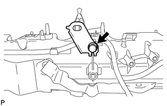
REMOVE VACUUM PUMP ASSEMBLY
-

Disconnect the vacuum hose.
-
Remove the 3 bolts and vacuum pump assembly.
-
Remove the 2 O-rings from the vacuum pump assembly.
-
-
REMOVE IDLER PULLEY COVER PLATE
-
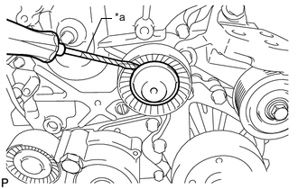
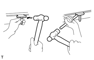
*a Tape Using a screwdriver, remove the idler pulley cover plate.
Tech Tips
Tape the screwdriver tip before use.
-
-
REMOVE NO. 1 IDLER PULLEY SUB-ASSEMBLY
-
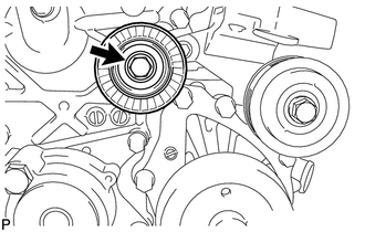
Remove the bolt and No. 1 idler pulley sub-assembly.
-
-
REMOVE NO. 2 IDLER PULLEY SUB-ASSEMBLY
-
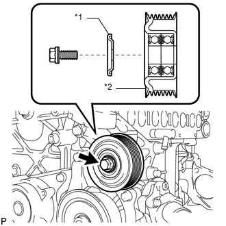
*1 No. 2 Idler Pulley Cover Plate *2 No. 2 Idler Pulley Sub-Assembly Remove the bolt, No. 2 idler pulley cover plate and No. 2 idler pulley sub-assembly.
-
-
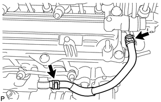
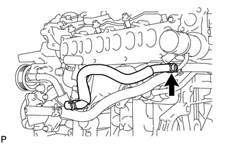
REMOVE NO. 4 WATER BY-PASS PIPE
-
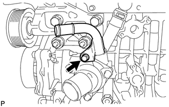
Remove the bolt and No. 4 water by-pass pipe from the water inlet housing.
-
Remove the O-ring from the No. 4 water by-pass pipe.
-
-
REMOVE ENGINE MOUNTING BRACKET
-
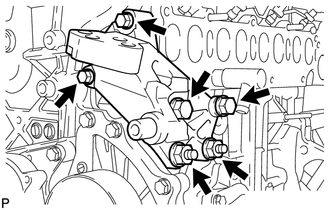
Remove the 4 bolts, 2 nuts and engine mounting bracket.
-
-
REMOVE V-RIBBED BELT TENSIONER ASSEMBLY
-
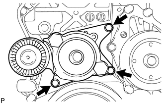
Remove the 3 bolts and V-ribbed belt tensioner assembly.
Note
As the heads of the bolts are not as thick as those of typical bolts, be careful not to damage them during removal.
-
-
REMOVE DIESEL THROTTLE BODY ASSEMBLY
-
REMOVE NO. 7 WATER BY-PASS HOSE
-
DISCONNECT NO. 8 WATER BY-PASS HOSE
-
REMOVE EGR VALVE BRACKET
-
REMOVE NO. 2 EGR PIPE SUB-ASSEMBLY
-
REMOVE ELECTRIC EGR CONTROL VALVE ASSEMBLY
-
REMOVE ENGINE OIL LEVEL DIPSTICK GUIDE
-
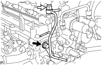
REMOVE FUEL INLET PIPE SUB-ASSEMBLY
-
REMOVE INJECTION PIPE SUB-ASSEMBLY
-
REMOVE NO. 4 FUEL HOSE
-
Slide the 2 clips and remove the No. 4 fuel hose.
-
-
REMOVE COMMON RAIL ASSEMBLY
-
REMOVE INTAKE MANIFOLD INSULATOR
-
REMOVE DIESEL TURBO PRESSURE SENSOR
-
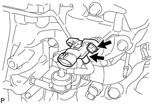
Disconnect the vacuum hose.
-
Remove the bolt and diesel turbo pressure sensor.
-
-
REMOVE NO. 1 GAS FILTER
-
REMOVE GAS FILTER BRACKET
-
REMOVE ENGINE COVER BRACKET
-
REMOVE NO. 2 INTAKE MANIFOLD
-
REMOVE INTAKE MANIFOLD
-
REMOVE WATER BY-PASS HOSE
-
REMOVE OIL COOLER ASSEMBLY
-
REMOVE NO. 6 WATER BY-PASS HOSE
-
Slide the clip and remove the No. 6 water by-pass hose from the outlet water pipe.
-
-
REMOVE NO. 8 WATER BY-PASS HOSE
-
Slide the clip and remove the No. 8 water by-pass hose from the outlet water pipe.
-
-
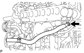
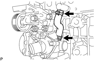
REMOVE NO. 3 WATER BY-PASS PIPE
-
Remove the 2 bolts and No. 3 water by-pass pipe.
-
Remove the O-ring from the No. 3 water by-pass pipe.
-
-
REMOVE NO. 1 TURBO OIL PIPE
-
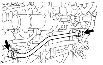
Remove the 2 union bolts, 2 gaskets and No. 1 turbo oil pipe.
-
-
REMOVE NO. 1 OIL COOLER BRACKET
-
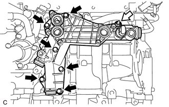

Nut Remove the 6 bolts, nut and No. 1 oil cooler bracket.
-
Remove the 3 gaskets from the No. 1 oil cooler bracket.
-
-
REMOVE NO. 1 CYLINDER BLOCK INSULATOR
-
Remove the No. 1 cylinder block insulator from the cylinder block sub-assembly.
-
-
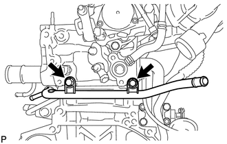
REMOVE NO. 2 WATER BY-PASS PIPE
-
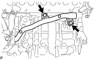
Remove the 2 bolts and No. 2 water by-pass pipe from the water inlet housing.
-
Remove the O-ring from the No. 2 water by-pass pipe.
-
-
REMOVE NO. 4 WATER BY-PASS HOSE
Slide the 2 clips and remove the No. 4 water by-pass hose.
-
REMOVE WATER INLET HOUSING
-
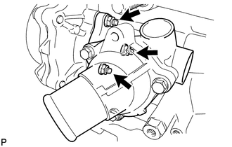
Remove the 3 nuts and water inlet housing.
-
Remove the gasket from the water inlet housing.
-
-
REMOVE FUEL HOSE PROTECTOR
-
REMOVE FUEL TUBE SUB-ASSEMBLY
-
REMOVE NO. 3 FUEL HOSE
-
REMOVE NO. 2 NOZZLE LEAKAGE PIPE
-
Check Valve Remove the check valve and gasket.
-
Remove the bolt and No. 2 nozzle leakage pipe.
-
-
REMOVE NO. 1 NOZZLE LEAKAGE PIPE
-
REMOVE NO. 1 NOZZLE HOLDER CLAMP
-
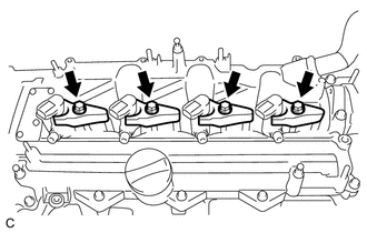
Remove the 4 bolts, 4 washers and 4 No. 1 nozzle holder clamps.
-
-
REMOVE INJECTOR ASSEMBLY
-
REMOVE NO. 1 VACUUM SWITCHING VALVE ASSEMBLY
-
REMOVE VACUUM TRANSMITTING HOSE ASSEMBLY
-
Disengage the 8 clamps and remove the 2 vacuum transmitting hose assemblies.
-
-
REMOVE NO. 1 WIRE HARNESS CLAMP BRACKET
-
Remove the bolt and No. 1 wire harness clamp bracket.
-
-
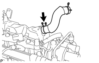
REMOVE VENTILATION HOSE
-
Slide the clip and remove the ventilation hose.
-
-
REMOVE CYLINDER HEAD COVER SUB-ASSEMBLY
-
Remove the oil filler cap sub-assembly.
-
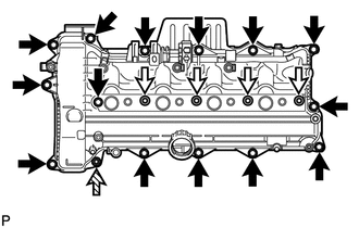
Nozzle Holder Clamp Seat 
Nut Remove the 4 nozzle holder clamp seats, 14 bolts, nut and cylinder head cover sub-assembly.
-
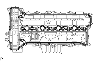
Remove the cylinder head cover gasket from the cylinder head cover sub-assembly.
-
-
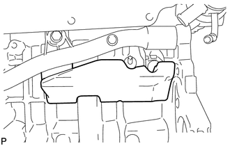
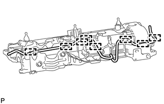
REMOVE OIL PAN SUB-ASSEMBLY
-
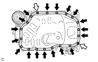
Nut Remove the 18 bolts and 2 nuts.
-
Insert the blade of an oil pan seal cutter between the oil pan sub-assembly and cylinder block sub-assembly, cut through the applied sealer and remove the oil pan sub-assembly.
Note
-
Do not use the oil pan seal cutter for the area between the oil pan and timing chain cover sub-assembly.
-
Be careful not to damage the contact surfaces of the oil pan sub-assembly.
-
-
-
REMOVE OIL FILTER ELEMENT
-
REMOVE OIL PRESSURE SWITCHING VALVE ASSEMBLY
-
REMOVE OIL FILTER BRACKET
-
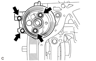
Remove the 4 bolts and oil filter bracket.
-
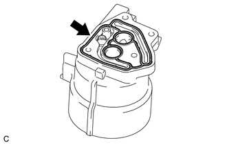
Remove the gasket from the oil filter bracket.
-
-
REMOVE OIL CHECK VALVE SUB-ASSEMBLY
-
Using a 5 mm hexagon wrench, remove the bolt and oil check valve sub-assembly from the oil filter bracket.
-
-
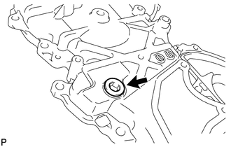
INSPECT OIL CHECK VALVE SUB-ASSEMBLY
-
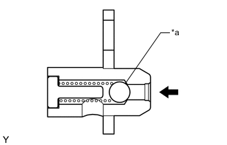
*a Ball Push the ball of the oil check valve sub-assembly to check if it is stuck.
If the check valve is stuck, replace the oil check valve sub-assembly.
-
-
REMOVE OIL STRAINER SUB-ASSEMBLY
-
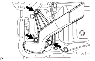
Remove the 3 bolts and oil strainer sub-assembly.
-
Remove the O-ring from the oil strainer sub-assembly.
-
-
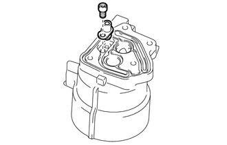
REMOVE CAMSHAFT POSITION SENSOR
-
DISCONNECT CRANKSHAFT POSITION SENSOR WIRE HARNESS
-
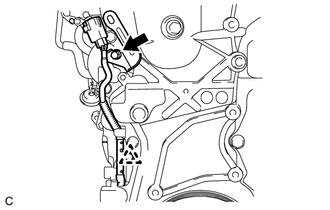
Remove the clip, bolt and disconnect the crankshaft position sensor wire harness.
-
-
REMOVE ENGINE WATER PUMP ASSEMBLY
-
REMOVE CRANKSHAFT PULLEY
-
REMOVE TIMING CHAIN COVER SUB-ASSEMBLY
-
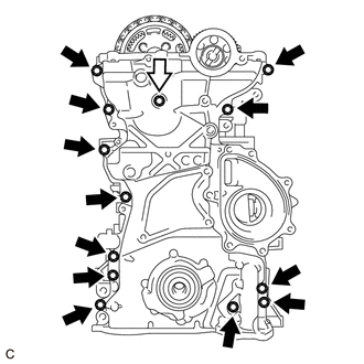
Bolt and Seal Washer Remove the 13 bolts and seal washer.
-
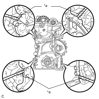
*a Protective Tape Remove the timing chain cover sub-assembly by prying between the timing chain cover sub-assembly and cylinder head sub-assembly, camshaft housing, cylinder block sub-assembly and stiffening crankcase with a screwdriver as shown in the illustration.
Note
Be careful not to damage the contact surfaces of the cylinder head sub-assembly, camshaft housing, cylinder block sub-assembly, stiffening crankcase and timing chain cover sub-assembly.
Tech Tips
Tape the screwdriver tip before use.
-
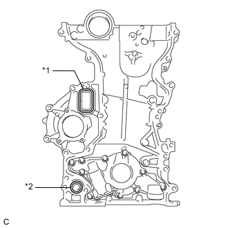
*1 Gasket *2 O-Ring Remove the gasket and O-ring from the timing chain cover sub-assembly.
-
-
REMOVE STRAIGHT SCREW PLUG
Tech Tips
Perform this procedure only when replacement of the straight screw plug.
-
Using a 10 mm socket hexagon wrench, remove the straight screw plug and gasket.
-
-
REMOVE FRONT CRANKSHAFT OIL SEAL
-
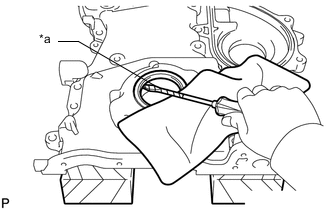
*a Protective Tape Place the timing chain cover sub-assembly on wooden blocks.
-
Using a screwdriver, pry out the front crankshaft oil seal.
Note
Do not damage the surface of the oil seal press fit hole.
Tech Tips
Tape the screwdriver tip before use.
-
-
REPLACE STUD BOLT
Tech Tips
If a stud bolt is deformed or its threads are damaged, replace it.
-
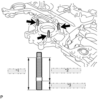
*1 34 mm (1.34 in.) *2 25 mm (0.984 in.) *3 9.0 mm (0.354 in.) Using an E6 "TORX" wrench, replace the 3 stud bolts.
- Torque:
- 3.0 N*m { 31 kgf*cm, 27 in.*lbf }
-