OIL PUMP(w/ Glow Plug Controller) INSPECTION
PROCEDURE
-
INSPECT OIL PUMP DRIVE AND DRIVEN ROTORS
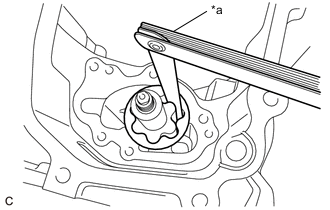
*a Feeler Gauge
-
Check the tip clearance.
-
Using a feeler gauge, measure the clearance between the tips of the oil pump drive rotor and oil pump driven rotor.
Standard Tip Clearance 0.08 to 0.16 mm (0.00315 to 0.00630 in.) Maximum Tip Clearance 0.21 mm (0.00827 in.) If the tip clearance is more than the maximum, replace the oil pump rotor set.
-
-
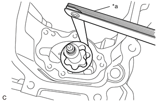
*a Feeler Gauge Check the body clearance.
-
Using a feeler gauge, measure the clearance between the oil pump driven rotor and oil pan sub-assembly.
Standard Body Clearance 0.10 to 0.18 mm (0.00394 to 0.00709 in.) Maximum Body Clearance 0.20 mm (0.00787 in.) If the body clearance is more than the maximum, replace the oil pump rotor set or oil pan sub-assembly.
-
-
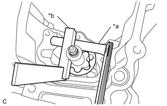
*a Feeler Gauge *b Steel Square Check the side clearance.
-
Using a feeler gauge and steel square, measure the clearance between the oil pump rotor set and steel square.
Standard Side Clearance 0.03 to 0.09 mm (0.00118 to 0.00354 in.) Maximum Side Clearance 0.15 mm (0.00591 in.) If the side clearance is more than the maximum, replace the oil pump rotor set or oil pan sub-assembly.
-
-