THERMOSTAT INSTALLATION
PROCEDURE
-
INSTALL THERMOSTAT
-
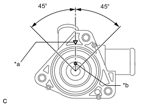
*a Mark *b Jiggle Valve Install the element to the water inlet as shown in the illustration.
Tech Tips
The jiggle valve may be set within 45° on either side of the prescribed position.
-
Install the spring to the water inlet.
-
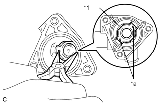
*1 Frame *a Protrusion Install the frame to the water inlet.
Tech Tips
Using needle nose pliers, push down on the frame to compress the spring. While the spring is compressed, turn the frame to engage it to the protrusions of the water inlet.
-
-
INSTALL NO. 2 WATER INLET HOUSING GASKET
-
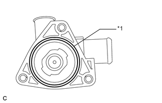
*1 No. 2 Water Inlet Housing Gasket Install a new No. 2 water inlet housing gasket to the water inlet.
-
-
INSTALL WATER INLET
-
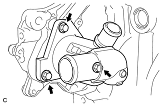
Install the water inlet with the 3 bolts.
- Torque:
- 10 N*m { 102 kgf*cm, 7 ft.*lbf }
-
-
CONNECT NO. 2 RADIATOR HOSE
-
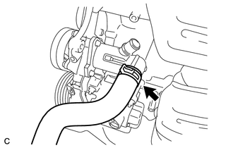
Connect the No. 2 radiator hose to the water inlet and slide the clip to secure it.
-
-
CONNECT NO. 1 WATER BY-PASS PIPE
-
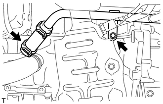
Connect the No. 1 water by-pass pipe and slide the clip to secure it.
-
Install the No. 1 water by-pass pipe with the bolt.
- Torque:
- 22 N*m { 224 kgf*cm, 16 ft.*lbf }
-
-
INSTALL OIL LEVEL DIPSTICK GUIDE SUB-ASSEMBLY
-
INSTALL GENERATOR ASSEMBLY (for 80A Type)
-
INSTALL GENERATOR ASSEMBLY (for 100A Type)
-
ADD ENGINE COOLANT
-
INSPECT FOR COOLANT LEAK