EXHAUST HEAT RECIRCULATION SYSTEM Exhaust Heat Recirculation System Circuit
DESCRIPTION
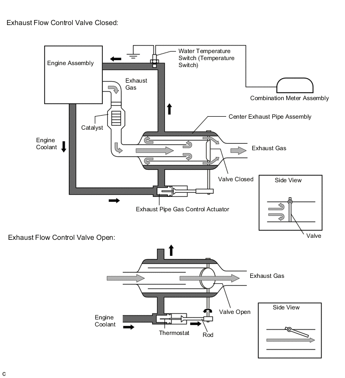
In the exhaust heat recirculation system, coolant is warmed up using conventionally wasted exhaust gas heat to accelerate engine warm-up time, enhancing fuel efficiency and heater performance. Since this system allows the engine to be warmed up with greater efficiency, vehicles equipped with the stop and start system are able to activate the stop and start system sooner, contributing to low fuel consumption.
The heat recirculator is positioned in the center exhaust pipe assembly after the catalyst. Coolant from the engine flows around the heat recirculator and then returns to the engine. If the engine is started while cold, the exhaust pipe gas control actuator rod is contracted and the exhaust flow control valve is closed, routing the exhaust gas around the heat recirculator to warm up the engine coolant.
After the engine coolant temperature rises and the engine has warmed up, the heat of the engine coolant expands the thermostat and the exhaust pipe gas control actuator rod extends. This opens the exhaust flow control valve to switch to the normal exhaust gas path.
The exhaust flow control valve can also be opened by exhaust gas pressure to prevent insufficient acceleration performance when the engine is cold. In addition, to monitor the engine coolant temperature, a water temperature switch is provided between the engine and heat recirculator. When the engine coolant temperature is normal, the water temperature switch is closed (turns on). If the engine coolant temperature is excessively high (overheating), the switch opens (turns off) and the water temperature receiver gauge in the combination meter assembly indicates the maximum reading* to inform the driver of the malfunction and DTC B1503 is stored.
*: The maximum reading varies depending on the combination meter type. On the analog meter, the needle of the gauge indicates above HI. On the multi-information display, the rightmost H side segment and water temperature hot warning light illuminate simultaneously.
PROCEDURE
-
CHECK HARNESS AND CONNECTOR (TEMPERATURE SWITCH - COMBINATION METER - BODY GROUND)
-
Disconnect the A119 temperature switch connector.
-
Disconnect the E46 combination meter assembly connector.
-
Measure the resistance according to the value(s) in the table below.
Standard Resistance (Check for Open) Tester Connection Condition Specified Condition A119-2 (TWS2) - E46-29 (TWS2) Always Below 1 Ω A119-1 (GND) - Body ground Always Below 1 Ω Standard Resistance (Check for Short) Tester Connection Condition Specified Condition A119-2 (TWS2) or E46-29 (TWS2) - Body ground Always 10 kΩ or higher -
Reconnect the E46 combination meter assembly connector.
-
Reconnect the A119 temperature switch connector.
Result Result OK NG
NG 
REPAIR OR REPLACE HARNESS OR CONNECTOR
OK 
-
-
CHECK COMBINATION METER ASSEMBLY
-
Turn the ignition switch to ON.
-
Disconnect the A119 temperature switch connector.
-
Check the water temperature receiver gauge in the combination meter assembly.
Result Result Proceed to Water temperature receiver gauge changes from the normal value to above HI (for Analog meter) A Water temperature receiver gauge changes from illumination of normal temperature segments to illumination of the rightmost H side segment (the water temperature hot warning light illuminates simultaneously) (for Multi-information display) Water temperature receiver gauge remains above HI even after the connector is disconnected (for Analog meter) B Water temperature receiver gauge rightmost H side segment is illuminated and remains unchanged (the water temperature hot warning light also remains illuminated) (for Multi-information display) Water temperature receiver gauge indicates the normal value and remains unchanged even after the connector is disconnected C -
Reconnect the A119 temperature switch connector.
A
SYSTEM OK
C
REPLACE COMBINATION METER ASSEMBLY for Sedan: Click here
REPLACE COMBINATION METER ASSEMBLY for Hatchback, Wagon: Click hereB
-
-
REPLACE TEMPERATURE SWITCH
-
Replace the temperature switch.
Result Result NEXT
NEXT
-
-
CHECK COMBINATION METER ASSEMBLY
-
Turn the ignition switch to ON.
-
Disconnect the A119 temperature switch connector.
-
Check the water temperature receiver gauge in the combination meter assembly.
Result Result Proceed to Water temperature receiver gauge changes from the normal value to above HI (for Analog meter) A Water temperature receiver gauge changes from illumination of normal temperature segments to illumination of the rightmost H side segment (the water temperature hot warning light illuminates simultaneously) (for Multi-information display) Water temperature receiver gauge remains above HI even after the connector is disconnected (for Analog meter) B Water temperature receiver gauge rightmost H side segment is illuminated and remains unchanged (the water temperature hot warning light also remains illuminated) (for Multi-information display) -
Reconnect the A119 temperature switch connector.
A
END
B
REPLACE COMBINATION METER ASSEMBLY for Sedan: Click here
REPLACE COMBINATION METER ASSEMBLY for Hatchback, Wagon: Click here -