EXHAUST MANIFOLD W/ TURBOCHARGER INSTALLATION
PROCEDURE
-
INSTALL EXHAUST MANIFOLD
-
Install 2 new gaskets to the cylinder head sub-assembly.
-
Temporarily install the exhaust manifold with the 8 nuts.
-
Tighten the 8 nuts of the exhaust manifold.
- Torque:
- 11 N*m { 112 kgf*cm, 8 ft.*lbf }
-
Tighten the 8 nuts again.
- Torque:
- 13 N*m { 133 kgf*cm, 10 ft.*lbf }
-
-
INSTALL EGR COOLER ASSEMBLY WITH EGR VALVE ASSEMBLY
-
INSTALL NO. 1 EXHAUST MANIFOLD HEAT INSULATOR
-
CONNECT FUEL FEED PIPE SUB-ASSEMBLY
-
CONNECT NO. 1 AIR TUBE ASSEMBLY
-
Connect the No. 1 air tube assembly to the manual transaxle assembly with the 2 bolts.
- Torque:
- 20 N*m { 204 kgf*cm, 15 ft.*lbf }
-
Connect the outlet heater water hose to the No. 2 radiator pipe, and slide the clamp to secure the hose.
-
Connect the water hose sub-assembly to the No. 1 radiator pipe, and slide the clamp to secure the hose.
-
Attach the clamp and connect the water hose sub-assembly to the compressor outlet elbow.
-
Connect the water by-pass hose assembly to the No. 2 radiator pipe, and slide the clamp to secure the hose.
-
Connect the radiator hose sub-assembly to the No. 1 radiator pipe, and slide the clamp to secure the hose.
-
-
INSTALL NO. 4 WATER BY-PASS HOSE
-
Install the No. 4 water by-pass hose to the No. 2 radiator pipe, and slide the clamp to secure the hose.
-
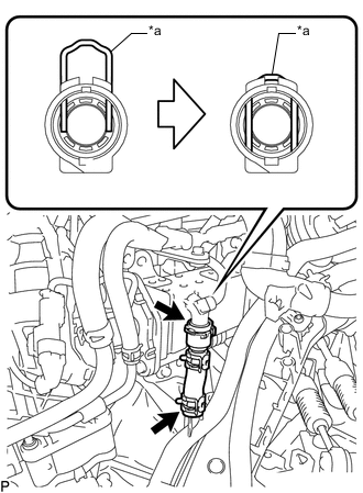
*a Retainer Connect the No. 4 water by-pass hose to the EGR cooler assembly and lock the retainer as shown in the illustration.
-
-
CONNECT ENGINE WIRE
-
Connect the engine wire to the No. 1 air tube assembly with the 2 bolts.
- Torque:
- 8.4 N*m { 86 kgf*cm, 74 in.*lbf }
-
Attach the 2 clamps to the No. 1 air tube assembly.
-
-
INSTALL TURBOCHARGER SUB-ASSEMBLY
-
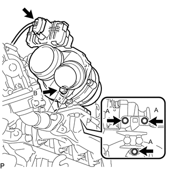
Temporarily install a new gasket, the turbocharger sub-assembly and the 3 bolts (A).
-
Temporarily install the bolt (B).
-
Tighten the 4 bolts.
- Torque:
- for Bolt (A)
- 25 N*m { 255 kgf*cm, 18 ft.*lbf }
- for Bolt (B)
- 10 N*m { 102 kgf*cm, 7 ft.*lbf }
-
Connect the connector to the turbocharger sub-assembly.
-
-
INSTALL NO. 1 EXHAUST MANIFOLD PIPE
-
Temporarily install the No. 1 exhaust manifold pipe with the bolt.
-
Temporarily install 2 new gaskets with the union bolt.
-
Tighten the bolt and union bolt.
- Torque:
- for Bolt
- 8.0 N*m { 82 kgf*cm, 71 in.*lbf }
- for Union Bolt
- 35 N*m { 357 kgf*cm, 26 ft.*lbf }
-
Connect the exhaust manifold pressure sensor connector.
-
-
CONNECT NO. 1 TURBO OIL PIPE
-
Connect the No. 1 turbo oil pipe and 2 new gaskets with the union bolt.
- Torque:
- 22 N*m { 224 kgf*cm, 16 ft.*lbf }
-
-
INSTALL TURBO OIL OUTLET PIPE
-
Install a new O-ring to the turbo oil outlet pipe.
-
Install a new gasket and the turbo oil outlet pipe with the 3 bolts.
- Torque:
- 10 N*m { 102 kgf*cm, 7 ft.*lbf }
-
-
CONNECT COMPRESSOR OUTLET ELBOW
-
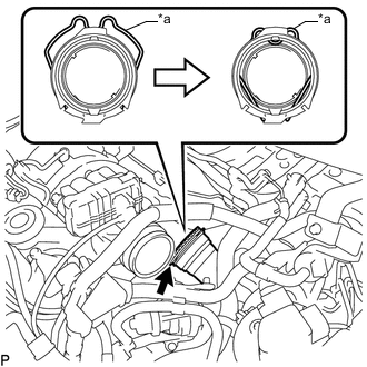
*a Retainer Connect the compressor outlet elbow to the turbocharger sub-assembly and lock the retainer as shown in the illustration.
-
-
INSTALL AIR CLEANER CASE SUB-ASSEMBLY
-
Install the air cleaner case sub-assembly with the 3 bolts.
- Torque:
- 7.0 N*m { 71 kgf*cm, 62 in.*lbf }
-
-
INSTALL AIR CLEANER CAP SUB-ASSEMBLY WITH AIR CLEANER HOSE ASSEMBLY
-
Install the air cleaner filter element sub-assembly to the air cleaner case sub-assembly.
-
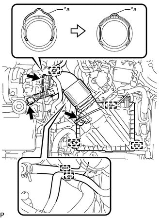
*a Retainer Connect the air cleaner hose assembly to the turbocharger sub-assembly and lock the retainer as shown in the illustration.
-
Attach the 2 clamps to install the air cleaner cap sub-assembly.
-
Connect the ventilation hose to the cylinder head cover sub-assembly.
-
Attach the clamp and connect the No. 2 fuel hose to the air cleaner hose assembly.
-
Attach the clamp and connect the No. 1 fuel hose to the air cleaner hose assembly.
-
Attach the clamp and connect the vacuum hose to the air cleaner hose assembly.
-
Attach the clamp and connect the mass air flow meter sub-assembly connector.
-
-
INSTALL BATTERY CARRIER
-
Install the battery carrier with the 4 bolts.
- Torque:
- 19 N*m { 194 kgf*cm, 14 ft.*lbf }
-
Attach the 2 clamps to connect the engine wire.
-
-
INSTALL BATTERY TRAY
-
INSTALL BATTERY
-
INSTALL BATTERY INSULATOR
-
INSTALL BATTERY CLAMP SUB-ASSEMBLY
-
Attach the hook of the battery clamp sub-assembly to the battery carrier.
-
Partially tighten the nut and temporarily install the bolt.
-
Adjust the battery clamp sub-assembly position.
-
Tighten the nut and bolt.
- Torque:
- for Bolt
- 17 N*m { 173 kgf*cm, 13 ft.*lbf }
- for Nut
- 3.5 N*m { 36 kgf*cm, 31 in.*lbf }
-
-
INSTALL EXHAUST MANIFOLD CONVERTER SUB-ASSEMBLY
-
CONNECT CABLE FROM POSITIVE BATTERY TERMINAL
-
CONNECT CABLE FROM NEGATIVE BATTERY TERMINAL
Note
When disconnecting the cable, some systems need to be initialized after the cable is reconnected.
-
ADD ENGINE COOLANT
-
INSPECT FOR COOLANT LEAK