INTERCOOLER INSTALLATION
PROCEDURE
-
INSTALL INTERCOOLER ASSEMBLY
-
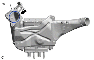
*a Protrusion Install a new throttle body gasket to the intercooler assembly with the protrusion of the throttle body gasket oriented as shown in the illustration.
-
Temporarily install the intercooler assembly to the air tube assembly with the hose clamp.
-
Temporarily install the intercooler assembly to the throttle body with motor assembly with the 2 bolts and 2 nuts.
-
Connect the No. 2 turbo water pipe sub-assembly to the intercooler assembly with the 2 bolts.
- Torque:
- 10 N*m { 102 kgf*cm, 7 ft.*lbf }
-
Connect the 2 No. 1 intercooler water hoses to the intercooler assembly and slide the 2 clips to secure them.
-
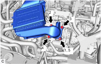
Tighten the 2 bolts and 2 nuts in the order shown in the illustration.
- Torque:
- 10 N*m { 102 kgf*cm, 7 ft.*lbf }
-
Tighten the hose clamp.
- Torque:
- 6.3 N*m { 64 kgf*cm, 56 in.*lbf }
-
-
CONNECT NO. 1 TURBO WATER HOSE
-
Connect the No. 1 turbo water hose to the intercooler assembly and slide the clip to secure it.
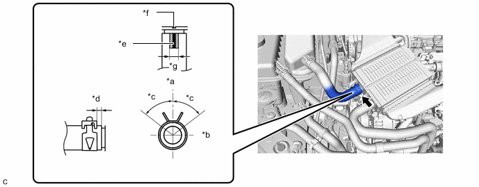
*a Upper *b Front *c 60° *d 2 to 5 mm (0.0787 to 0.197 in.) *e Paint Mark *f Matchmark *g Paint Mark Area - - Tech Tips
-
Position the No. 1 turbo water hose and clip as shown in the illustration.
-
Push in the No. 1 turbo water hose until it contacts the stopper.
-
-
-
CONNECT NO. 4 TURBO WATER HOSE
-
Connect the No. 4 turbo water hose to the intercooler assembly and slide the clip to secure it.
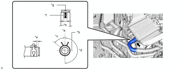
*a Upper *b Front *c 60° *d 180° *e 2 to 5 mm (0.0787 to 0.197 in.) *f Paint Mark *g Matchmark *h Paint Mark Area Tech Tips
-
Position the No. 4 turbo water hose and clip as shown in the illustration.
-
Push in the No. 4 turbo water hose until it contacts the stopper.
-
-
-
INSTALL NO. 1 TURBO PRESSURE SENSOR
-
INSTALL NO. 1 ENGINE COVER SUB-ASSEMBLY
-
ADD COOLANT (for Intercooler)
-
INSPECT FOR COOLANT LEAK (for Intercooler)