LIGHTING SYSTEM, Diagnostic DTC:B1244
| DTC Code | DTC Name |
|---|---|
| B1244 | Light Sensor Circuit Malfunction |
DESCRIPTION
The automatic light control sensor*1 or rain sensor*2 detects ambient light, converts it into an electrical signal and outputs it to the main body ECU. The main body ECU turns the headlights and taillights on or off according to the signal.
-
*1: w/o Rain Sensor
-
*2: w/ Rain Sensor
| DTC Code | DTC Detection Condition | Trouble Area |
|---|---|---|
| B1244 | Either condition is met:
|
|
WIRING DIAGRAM
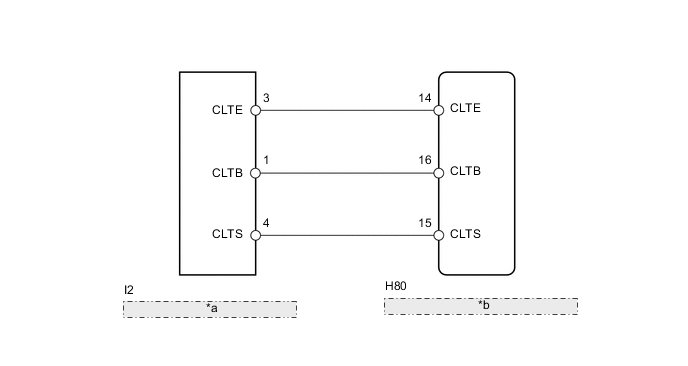
| *a | Automatic Light Control Sensor |
| *b | Main Body ECU (Instrument Panel Junction Block Assembly) |
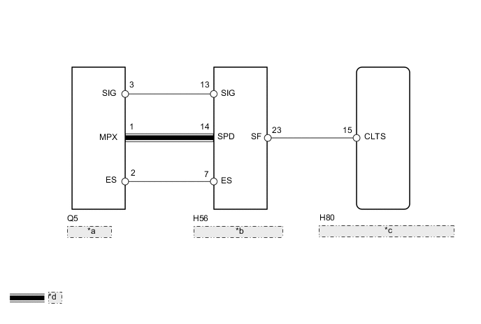
| *a | Rain Sensor |
| *b | Windshield Wiper Relay |
| *c | Main Body ECU (Instrument Panel Junction Block Assembly) |
| *d | LIN Communication Line |
PROCEDURE
-
CHECK FOR DTC
-
Clear the DTCs Click here.
-
Check for DTCs Click here.
OK DTC B1244 output does not occur.
OK 
USE SIMULATION METHOD TO CHECK Click here
NG 
-
-
CHECK VEHICLE TYPE
-
Check vehicle type.
Result Result Proceed to w/ Rain Sensor A w/o Rain Sensor B
B 
READ VALUE USING INTELLIGENT TESTER (AUTOMATIC LIGHT CONTROL SENSOR) Click here
A
-
-
CHECK AUTOMATIC WIPER FUNCTION
-
Check the automatic wiper system.
-
Turn the wiper switch to the AUTO position.
-
With the rain sensor installed to the windshield, sprinkle water on the windshield around the rain sensor. Check if the wipers operate.
OK The wipers operate.
-
NG
GO TO WIPER AND WASHER SYSTEM Click here
OK
-
-
CHECK AUTOMATIC LIGHT CONTROL FUNCTION
-
Check the automatic light control system.
-
Turn the light control switch to the AUTO position.
-
With the rain sensor installed to the windshield, cover the rain sensor with a hand. Check if the headlights operate.
OK The headlights operate. Tech Tips
The sensitivity of the automatic light control system can be adjusted using the customize function. Make sure that the sensitivity setting is NORMAL before performing this check.
-
OK
USE SIMULATION METHOD TO CHECK Click here
NG
-
-
CHECK HARNESS AND CONNECTOR (MAIN BODY ECU - WINDSHIELD WIPER RELAY ASSEMBLY)
-
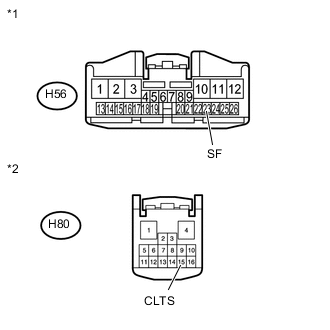
Text in Illustration *1 Front view of wire harness connector
(to Windshield Wiper Relay)
*2 Front view of wire harness connector
(to Main Body ECU)
Disconnect the H56 windshield wiper relay connector and H80 main body ECU connector.
-
Measure the resistance according to the value(s) in the table below.
Standard Resistance Tester Connection Condition Specified Condition H80-15 (CLTS) - H56-23 (SF) Always Below 1 Ω H80-15 (CLTS) - Body ground Always 10 kΩ or higher
NG
REPAIR OR REPLACE HARNESS OR CONNECTOR
OK
-
-
CHECK WINDSHIELD WIPER RELAY ASSEMBLY
-
Reconnect the H56 windshield wiper relay connector and H80 main body ECU connector.
-
Connect an oscilloscope to the rain sensor connector.
-
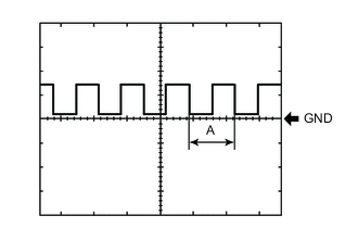
Check the waveform.
OK Tester Connection Switch Condition Specified Condition H56-23 (SF) - Body ground Ignition switch ON Pulse generation (See waveform 1)
-
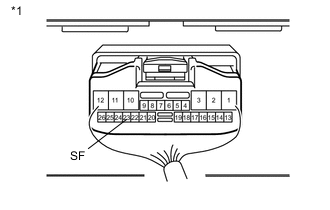
Text in Illustration *1 Component with harness connected
(Windshield Wiper Relay)
Waveform 1
Item Content Tool setting 5 V/DIV., 10 ms./DIV. Tech Tips
If the ambient light becomes brighter, width A becomes narrower.
Result Result Proceed to OK A NG (for LHD) B NG (for RHD) C
-
A
REPLACE MAIN BODY ECU (INSTRUMENT PANEL JUNCTION BLOCK ASSEMBLY)
B
REPLACE WINDSHIELD WIPER RELAY ASSEMBLY Click here
C
REPLACE WINDSHIELD WIPER RELAY ASSEMBLY Click here
-
-
READ VALUE USING INTELLIGENT TESTER (AUTOMATIC LIGHT CONTROL SENSOR)
-
Using the intelligent tester, read the Data List Click here.
Main Body Tester Display Measurement Item/Range Normal Condition Diagnostic Note Illumination Rate Info Light control sensor illuminance / 0 to 65535 lx Value is output according to ambient light level - OK Normal condition listed above is displayed.
OK
REPLACE MAIN BODY ECU (INSTRUMENT PANEL JUNCTION BLOCK ASSEMBLY)
NG
-
-
CHECK HARNESS AND CONNECTOR (MAIN BODY ECU - AUTOMATIC LIGHT CONTROL SENSOR)
-
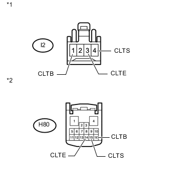
Text in Illustration *1 Front view of wire harness connector
(to Automatic Light Control Sensor)
*2 Front view of wire harness connector
(to Main Body ECU)
Disconnect the H80 main body ECU connector.
-
Disconnect the I2 automatic light control sensor connector.
-
Measure the resistance according to the value(s) in the table below.
Standard Resistance Tester Connection Condition Specified Condition H80-14 (CLTE) - I2-3 (CLTE) Always Below 1 Ω H80-15 (CLTS) - I2-4 (CLTS) Always Below 1 Ω H80-16 (CLTB) - I2-1 (CLTB) Always Below 1 Ω H80-14 (CLTE) - Body ground Always 10 kΩ or higher H80-15 (CLTS) - Body ground Always 10 kΩ or higher H80-16 (CLTB) - Body ground Always 10 kΩ or higher
NG
REPAIR OR REPLACE HARNESS OR CONNECTOR
OK
-
-
CHECK MAIN BODY ECU (INSTRUMENT PANEL JUNCTION BLOCK ASSEMBLY)
-
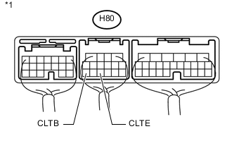
Text in Illustration *1 Component with harness connected
(Main Body ECU)
Remove the main body ECU with the connector(s) still connected.
-
Measure the voltage according to the value(s) in the table below.
Standard Voltage Tester Connection Switch Condition Specified Condition H80-16 (CLTB) - H80-14 (CLTE) Ignition switch off Below 1 V Ignition switch ON 11 to 14 V
NG
REPLACE MAIN BODY ECU (INSTRUMENT PANEL JUNCTION BLOCK ASSEMBLY)
OK
-
-
INSPECT AUTOMATIC LIGHT CONTROL SENSOR
-
Check the automatic light control sensor Click here.
OK
REPLACE MAIN BODY ECU (INSTRUMENT PANEL JUNCTION BLOCK ASSEMBLY)
NG
REPLACE AUTOMATIC LIGHT CONTROL SENSOR Click here
-