LIGHTING SYSTEM Warning Light Circuit
DESCRIPTION
The headlight beam level control system warning light in the combination meter assembly comes on for approximately 3 seconds when the ignition switch is turned to ON. The warning light also comes on when the headlight leveling ECU detects a malfunction.
WIRING DIAGRAM
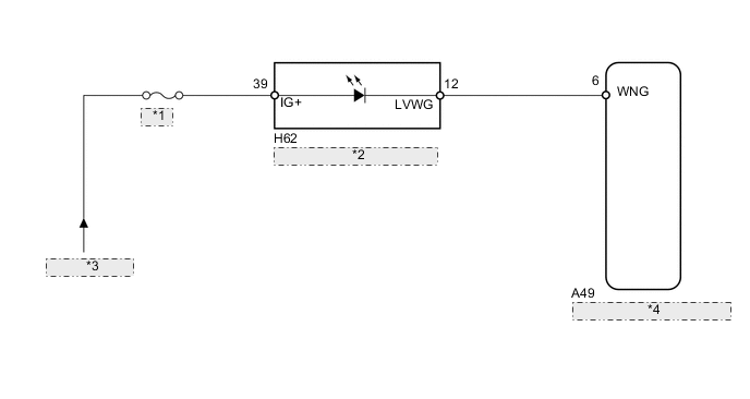
| *1 | METER |
| *2 | Combination Meter Assembly |
| *3 | from IG2 Relay |
| *4 | Headlight Leveling ECU Assembly |
PROCEDURE
-
INSPECT COMBINATION METER ASSEMBLY
-
Remove the combination meter assembly Click here.
-
Connect the positive (+) lead from the battery to terminal 39 (IG+) and the negative (-) lead to terminal 12 (LVWG).
-
Check that the warning light comes on.
OK Warning light comes on.
NG 
REPLACE COMBINATION METER ASSEMBLY Click here
OK 
-
-
CHECK HARNESS AND CONNECTOR (BATTERY - COMBINATION METER ASSEMBLY)
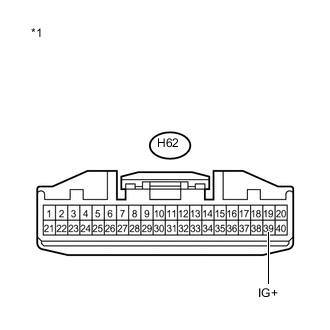
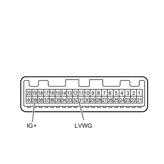
Text in Illustration *1 Front view of wire harness connector
(to Combination Meter Assembly)
-
Disconnect the H62 combination meter connector.
-
Measure the voltage according to the value(s) in the table below.
Standard Voltage Tester Connection Switch Condition Specified Condition H62-39 (IG+) - Body ground Ignition switch ON 11 to 14 V Ignition switch off Below 1 V
NG
REPAIR OR REPLACE HARNESS OR CONNECTOR
OK
-
-
CHECK HARNESS AND CONNECTOR (COMBINATION METER ASSEMBLY - HEADLIGHT LEVELING ECU ASSEMBLY)
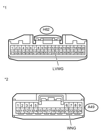
Text in Illustration *1 Front view of wire harness connector
(to Combination Meter Assembly)
*2 Front view of wire harness connector
(to Headlight Leveling ECU Assembly)
-
Disconnect the A49 ECU connector.
-
Measure the resistance according to the value(s) in the table below.
Standard Resistance Tester Connection Condition Specified Condition A49-6 (WNG) - H62-12 (LVWG) Always Below 1 Ω A49-6 (WNG) - Body ground Always 10 kΩ or higher
OK
PROCEED TO NEXT SUSPECTED AREA SHOWN IN PROBLEM SYMPTOMS TABLE Click here
NG
REPAIR OR REPLACE HARNESS OR CONNECTOR
-