LIGHTING SYSTEM LVL Terminal Circuit
DESCRIPTION
-
When terminals LVL and CG of the DLC3 are connected, the headlight leveling ECU initializes the height control sensor signal.
WIRING DIAGRAM
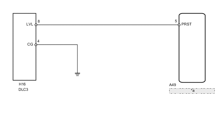
| *a | Headlight Leveling ECU Assembly |
PROCEDURE
-
CHECK HARNESS AND CONNECTOR (DLC3 - HEADLIGHT LEVELING ECU ASSEMBLY)
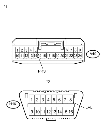
Text in Illustration *1 Front view of wire harness connector
(to Headlight Leveling ECU Assembly)
*2 DLC3
-
Disconnect the A49 ECU connector.
-
Measure the resistance according to the value(s) in the table below.
Standard Resistance Tester Connection Condition Specified Condition A49-5 (PRST) - H16-8 (LVL) Always Below 1 Ω A49-5 (PRST) - Body ground Always 10 kΩ or higher
NG 
REPAIR OR REPLACE HARNESS OR CONNECTOR
OK 
-
-
CHECK HARNESS AND CONNECTOR (DLC3 - BODY GROUND)
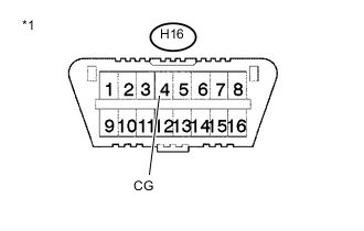
Text in Illustration *1 DLC3
-
Measure the resistance according to the value(s) in the table below.
Standard Resistance Tester Connection Condition Specified Condition E16-4 (CG) - Body ground Always Below 1 Ω
OK
PROCEED TO NEXT SUSPECTED AREA SHOWN IN PROBLEM SYMPTOMS TABLE Click here
NG
REPAIR OR REPLACE HARNESS OR CONNECTOR
-