WIPER AND WASHER SYSTEM(w/ Rain Sensor) TERMINALS OF ECU
-
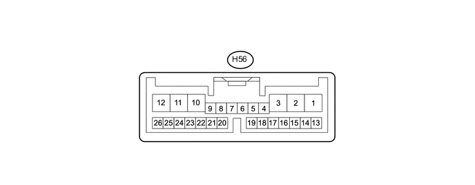
CHECK WINDSHIELD WIPER RELAY ASSEMBLY
-
Disconnect the H56 relay connector.
-
Measure the voltage and resistance according to the value(s) in the table below.
Terminal No. (Symbol) Wiring Color Terminal Description Condition Specified Condition H56-25 (W) - Body ground W - Body ground Front washer switch signal Front washer switch on Below 1 Ω Front washer switch off 10 kΩ or higher H56-8 (VR2) - H56-21 (VR1) Y - G Adjusting ring signal Windshield wiper switch adjusting ring* changed from (+) side to (-) side Below 10 to 2700 Ω H56-2 (IG) - Body ground L - Body ground Power source Ignition switch ON 11 to 14 V Ignition switch off Below 1 V H56-12 (E) - Body ground BR - Body ground Ground Always Below 1 Ω Tech Tips
*: The rain sensor sensitivity can be adjusted by the windshield wiper switch assembly adjusting ring.
-
If the result is not as specified, there may be a malfunction on the wire harness side.
-
-
Reconnect the H56 relay connector.
-
Measure the voltage according to the value(s) in the table below.
Terminal No. (Symbol) Wiring Color Terminal Description Condition Specified Condition H56-10 (+1) - Body ground G - Body ground Front wiper motor LO speed signal Front wiper motor in LO operation 11 to 14 V Front wiper motor off Below 1 V H56-11 (+2) - Body ground GR - Body ground Front wiper motor HI speed signal Front wiper motor in HI operation 11 to 14 V Front wiper motor off Below 1 V H56-25 (W) - Body ground W - Body ground Front washer motor signal Front washer switch on Below 1 V Front washer switch off 11 to 14 V H56-1 (+SM) - Body ground G - Body ground Front wiper motor operation signal Front wiper motor in LO or HI operation 11 to 14 V Front wiper motor off Below 1 V H56-3 (C1) - H56-15 (CO) BE - L IG signal Ignition switch ON 11 to 14 V Ignition switch off Below 1 V H56-13 (SIG) - H56-7 (ES) P - LG Power source Ignition switch ON 11 to 14 V Ignition switch off Below 1 V
-
If the result is not as specified, the windshield wiper relay may have a malfunction.
-
-
-
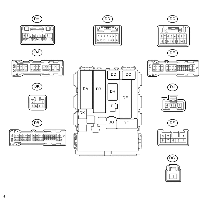
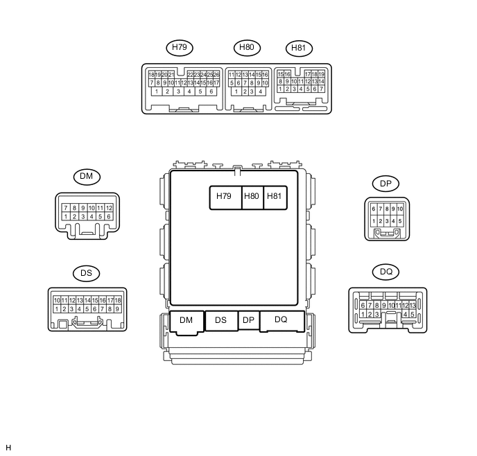
CHECK MAIN BODY ECU (INSTRUMENT PANEL JUNCTION BLOCK ASSEMBLY)
-
Disconnect the DB, DE, DF, DG and H80 ECU connectors.
-
Measure the resistance and voltage according to the value(s) in the table below.
Terminal No. (Symbol) Wiring Color Terminal Description Condition Specified Condition DB-30 (BECU) - Body ground W - Body ground ECU power supply (from battery) Always 11 to 14 V DG-1 (IG) - Body ground W - Body ground IG signal Ignition switch off Below 1 V Ignition switch ON 11 to 14 V DF-5 (ACC) - Body ground W - Body ground ACC signal Ignition switch off Below 1 V Ignition switch ACC 11 to 14 V DE-28 (GND1) - Body ground W-B - Body ground Ground Always Below 1 Ω H80-4 (GND2) - Body ground W-B - Body ground Ground Always Below 1 Ω
-
If the result is not as specified, there may be a malfunction on the wire harness side.
-
-
Reconnect the DB, DE, DF, DG and H80 ECU connectors.
-
Measure the voltage according to the value(s) in the table below.
Terminal No. (Symbol) Wiring Color Terminal Description Condition Specified Condition H81-19 (HDLO) - Body ground*1, *2 G - Body ground Low beam headlight operation signal Low beam headlights not operating Below 1 V Low beam headlights operating 11 to 14 V H79-20 (HRLY) - Body ground*2 B - Body ground Headlight cleaner switch operation signal Headlight cleaner switch off 11 to 14 V Headlight cleaner switch on Below 1 V
-
*1: for HID Headlight
-
*2: w/ Headlight Cleaner System
-
If the result is not as specified, the ECU may have a malfunction.
-
-
-
CHECK HEADLIGHT CLEANER CONTROL RELAY(w/ Headlight Cleaner System)

-
Disconnect the A67 relay connector.
-
Measure the resistance and voltage according to the value(s) in the table below.
Terminal No. (Symbol) Wiring Color Terminal Description Condition Specified Condition A67-3 (IG) - Body ground G - Body ground IG signal Ignition switch off Below 1 V Ignition switch ON 11 to 14 V A67-4 (E) - Body ground W-B - Body ground Ground Always Below 1 Ω A67-1 (HDLO) - Body ground* SB - Body ground Low beam headlight operation signal Low beam headlights not operating Below 1 V Low beam headlights operating 11 to 14 V A67-2 (H) - Body ground R - Body ground Headlight cleaner switch operation signal Headlight cleaner switch on 11 to 14 V Headlight cleaner switch off Below 1 V A67-6 (PB) - Body ground B - Body ground Headlight cleaner motor signal Always 11 to 14 V A67-5 (FRWA) - Body ground* W - Body ground Front washer motor operation signal Front washer switch off 11 to 14 V Front washer switch on Below 1 V
-
*: for HID Headlight
-
If the result is not as specified, there may be a malfunction on the wire harness side.
-
-