LOWER INSTRUMENT PANEL INSTALLATION
CAUTION / NOTICE / HINT
Tech Tips
-
Use the same procedure for RHD and LHD vehicles.
-
The procedure listed below is for LHD vehicles.
PROCEDURE
-
INSTALL GLOVE COMPARTMENT DOOR LOCKCYLINDER ASSEMBLY (for RHD)
-
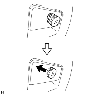
Insert the end of the glove compartment door lock cylinder as shown in the illustration, hold down the stopper and install the glove compartment door lock cylinder.
-
-
INSTALL GLOVE COMPARTMENT DOOR STOPPER SUB-ASSEMBLY
-
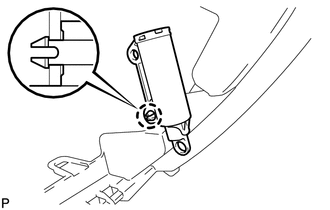
Attach the claw to install the glove compartment door stopper.
-
-
INSTALL LOWER INSTRUMENT PANEL SUB-ASSEMBLY
-
for LHD:
-
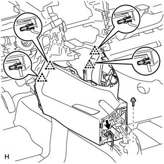
Attach the 6 guides to install the lower instrument panel.
-
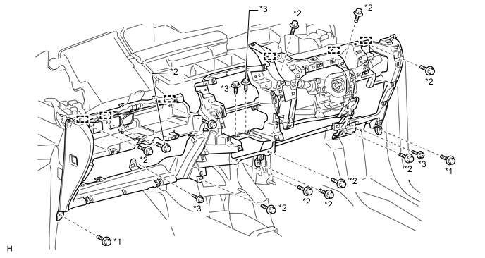
Install the 4 screws <D> and 2 bolts <B>.
-
Install the 11 bolts <C>.
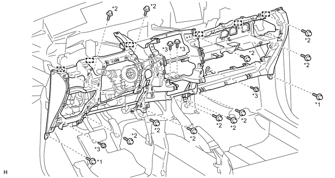
Text in Illustration *1 Bolt <B> *2 Bolt <C> *3 Screw <D> - - -
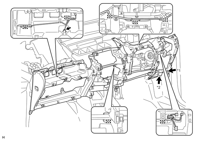
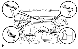
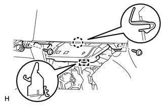
Connect the connectors and clamps.
-
Connect the hood lock control cable and DLC3.
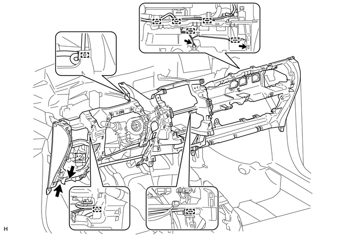
Text in Illustration *1 Hood Lock Control Cable *2 DLC3
-
-
for RHD:
-
Attach the 6 guides to install the lower instrument panel.
-
Install the 4 screws <D> and 2 bolts <B>.
-
Install the 11 bolts <C>.
Text in Illustration *1 Bolt <B> *2 Bolt <C> *3 Screw <D> - - -
Connect the connector and clamps.
-
Connect the hood lock control cable and DLC3.
Text in Illustration *1 Hood Lock Control Cable *2 DLC3
-
-
except Manual Transaxle:
-
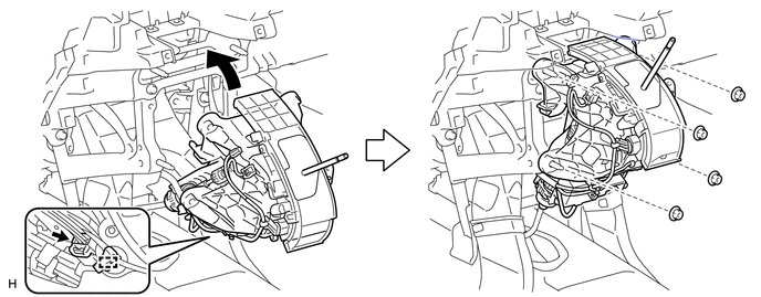
Connect the connector and attach the clamp.
-
Install the shift lever assembly with the 4 nuts.
-
-
for Manual Transaxle:
-
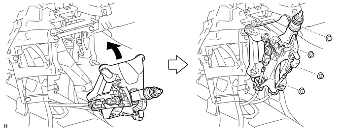
Install the shift lever assembly with the 4 nuts.
-
-
-
INSTALL LOWER NO. 1 INSTRUMENT PANEL FINISH PANEL
-
Attach the 4 clips to install the lower No. 1 instrument panel finish panel.
-
Connect the connector.
-
Install the screw <D>.
-
-
INSTALL FRONT NO. 2 CONSOLE BOX INSERT
-
Attach the 3 claws and guide to install the front No. 2 console box insert.
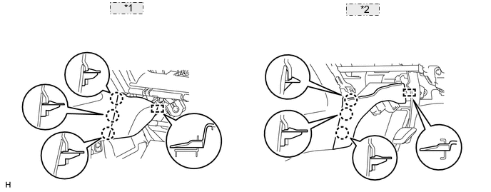
*1 for LHD: *2 for RHD:
-
-
INSTALL FRONT NO. 1 CONSOLE BOX INSERT
-
Attach the 3 claws and guide to install the front No. 1 console box insert.
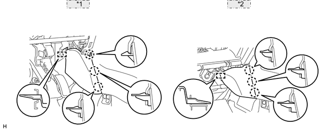
*1 for LHD: *2 for RHD:
-
-
INSTALL AIR CONDITIONER CONTROL ASSEMBLY (for Automatic Air Conditioning System)
-
INSTALL CENTER INSTRUMENT CLUSTER FINISH PANEL ASSEMBLY (for Manual Air Conditioning System)
-
INSTALL GLOVE COMPARTMENT DOOR ASSEMBLY
-
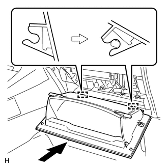
Attach the 2 hinges to install the glove compartment door.
-
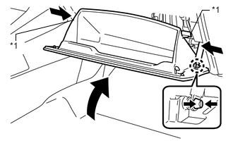
Attach the glove compartment door stopper to the glove compartment door as shown in the illustration.
-
While pushing in the sides of the glove compartment door as indicated by the arrows in the illustration, close the glove compartment door to engage the 2 stoppers.
Text in Illustration *1 Stopper
-
-
INSTALL NO. 2 INSTRUMENT PANEL UNDER COVER SUB-ASSEMBLY
-
Attach the 3 claws and guide to install the No. 2 instrument panel under cover.
-
-
INSTALL LOWER NO. 1 INSTRUMENT PANEL AIRBAG ASSEMBLY
-
INSTALL FUSE BOX OPENING COVER
-
for LHD:
-
Connect the connectors.
-
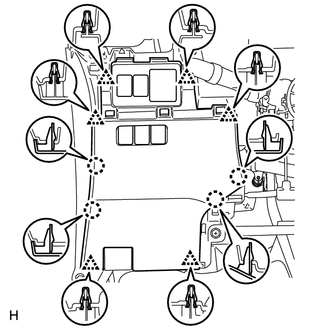
Attach the 6 clips and 4 claws to install the fuse box opening cover.
-
-
for RHD:
-
Connect the connectors.
-
Attach the 5 clips and 4 claws to install the fuse box opening cover.
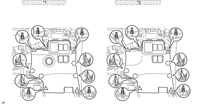
*1 w/ Entry and Start System: *2 w/o Entry and Start System:
-
-
-
INSTALL NO. 1 INSTRUMENT PANEL UNDER COVER SUB-ASSEMBLY
-
Attach the claw and guide to install the No. 1 instrument panel under cover.
-
Install the 2 screws <A>.
-
-
INSTALL UPPER STEERING COLUMN COVER
-
INSTALL LOWER STEERING COLUMN COVER
-
INSTALL STEERING WHEEL ASSEMBLY
-
INSTALL STEERING PAD
-
INSTALL BOX PANEL SUB-ASSEMBLY
-
Install the box panel sub-assembly Click here.
-
-
INSTALL INSTRUMENT PANEL SAFETY PAD SUB-ASSEMBLY
-
Install the instrument panel safety pad sub-assembly Click here.
-
-
CONNECT CABLE TO NEGATIVE BATTERY TERMINAL
Note
When disconnecting the cable, some systems need to be initialized after the cable is reconnected Click here.
-
CHECK SRS WARNING LIGHT
-
Check the SRS warning light Click here.
-