FRONT EVAPORATOR TEMPERATURE SENSOR REASSEMBLY
CAUTION / NOTICE / HINT
Tech Tips
-
Use the same procedure for RHD and LHD vehicles.
-
The procedure listed below is for LHD vehicles.
PROCEDURE
-
INSTALL NO. 1 COOLER THERMISTOR
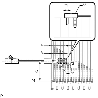
Text in Illustration *1 1 Fin *2 Sensor Part *3 Part Used to Hold Sensor in Place *4 from Tank *5 No. 1 Cooler Thermistor Note
If reusing the evaporator, do not insert the thermistor into a location where the thermistor was previously inserted.
-
Insert the thermistor to a location that is 1 fin to the right or left of its previous location.
Standard Item Specified Condition A 34.3 mm (1.35 in.) B 20.9 mm (1.97 in.) C 50 mm (1.97 in.)
-
-
INSTALL NO. 1 COOLER EVAPORATOR SUB-ASSEMBLY
-
Sufficiently apply compressor oil to 2 new O-rings and the O-ring fitting surfaces. Install the 2 O-rings to the No. 1 cooler evaporator sub-assembly.
for HFC-134a(R134a): Compressor oil ND-OIL 8 or equivalent for HFO-1234yf(R1234yf): Compressor oil ND-OIL 12 or equivalent Note
Keep the O-rings and O-ring fitting surfaces free from dirt or any foreign objects.
-
Install the No. 1 cooler evaporator sub-assembly together with the No. 1 cooler thermistor.
-
Attach the clamp.
-
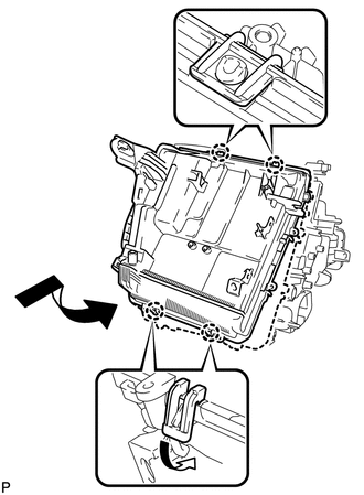
Attach the 4 claws as shown in the illustration.
-
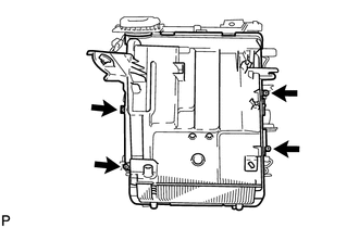
Install the lower heater case with the 4 screws.
-
-
INSTALL COOLER EXPANSION VALVE
-
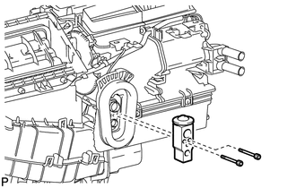
Using a 4 mm hexagon wrench, install the cooler expansion valve with the 2 hexagon bolts.
- Torque:
- 3.5 N*m { 36 kgf*cm, 31 in.*lbf }
-
-
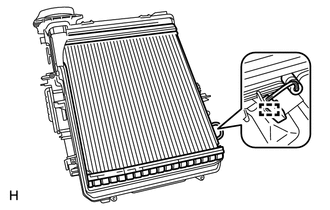
INSTALL HEATER RADIATOR UNIT SUB-ASSEMBLY
-
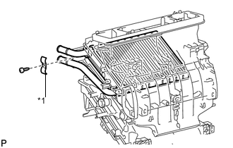
Text in Illustration *1 Clamp Install the heater radiator unit sub-assembly to the air conditioning unit assembly.
-
Install the clamp with the screw.
-
-
INSTALL DRAIN COOLER HOSE
-
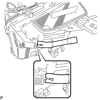
Install the drain cooler hose to the air conditioning unit assembly.
-
-
INSTALL AIR CONDITIONING DUCT SUB-ASSEMBLY (for Automatic Air Conditioning System)
-
Attach the 2 claws to install the air conditioning duct sub-assembly.
-
-
INSTALL AIR CONDITIONING AMPLIFIER ASSEMBLY
-
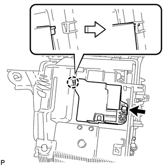
Attach the claw.
-
Install the air conditioning amplifier assembly with the screw.
-
-
INSTALL CONSOLE MOUNTING BRACKET LH
-
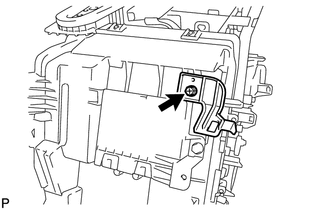
Install the console mounting bracket LH with the screw.
-
-
INSTALL UPPER CONSOLE MOUNTING BRACKET
-
Attach the 2 claws to install the upper console mounting bracket.
-
-
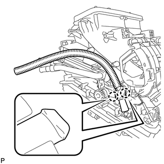
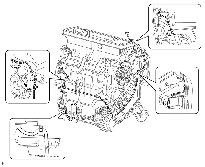
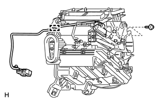
INSTALL AIR CONDITIONING HARNESS ASSEMBLY (for Automatic Air Conditioning System)
-
Connect the connector.
-
Attach each clamp to install the air conditioning harness assembly.
-
-
INSTALL QUICK HEATER ASSEMBLY (w/ PTC Heater)
-
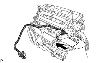
Install the quick heater assembly as shown in the illustration.
-
Install the 2 screws.
-
Attach the clamp.
-
-
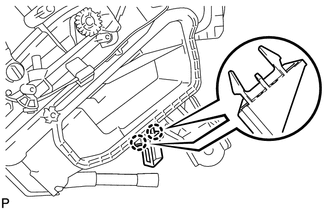
INSTALL AIR MIX DAMPER CONTROL CABLE SUB-ASSEMBLY (for Manual Air Conditioning System)
-
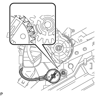
Set the control cable so that the teeth of the gear engage with the cutout part as shown in the illustration and attach the claw to install the control cable.
-
-
INSTALL NO. 2 HEATER CONTROL CABLE SUB-ASSEMBLY (for Manual Air Conditioning System)
-
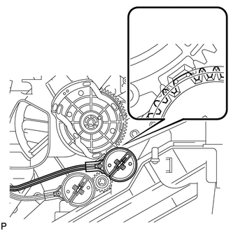
Set the control cable so that the tooth of the gear engages with the cutout part as shown in the illustration and attach the claw to install the control cable.
-
-
INSTALL AIR MIX DAMPER SERVO SUB-ASSEMBLY (for Automatic Air Conditioning System)
-
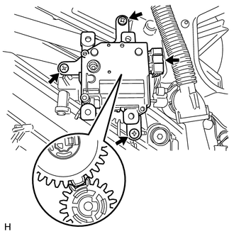
Set the air mix control servo motor so that the tooth of the gear engages with the cutout part as shown in the illustration to install the air mix control servo motor.
-
Install the 3 screws.
-
Connect the connector.
-
-
INSTALL NO. 2 AIR MIX DAMPER SERVO SUB-ASSEMBLY (for Automatic Air Conditioning System)
-
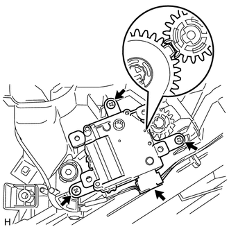
Set the air mix control servo motor so that the tooth of the gear engages with the cutout part as shown in the illustration to install the air mix control servo motor.
-
Install the 3 screws.
-
Connect the connector.
-
-
INSTALL MODE DAMPER SERVO SUB-ASSEMBLY (for Automatic Air Conditioning System)
-
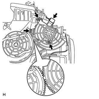
Set the air outlet control servo motor so that the tooth of the gear engages with the cutout part as shown in the illustration to install the air outlet control servo motor.
-
Install the 3 screws.
-
Connect the connector.
-