HEATER SWITCH(w/ Combustion Type Power Heater) INSPECTION
PROCEDURE
-
INSPECT HEATER SWITCH ASSEMBLY
-
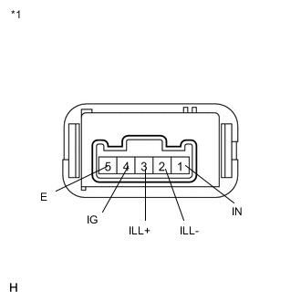
Text in Illustration *1 Component without harness connected
(Heater Switch Assembly)
Disconnect the connector from the heater switch assembly.
-
Measure the resistance according to the value(s) in the table below.
Standard Resistance Tester connection Condition Specified condition 4 (IG) - 1 (IN) Heater switch ON Below 1 Ω 4 (IG) - 1 (IN) Heater switch OFF 10 kΩ or higher If the result is not as specified, replace the heater switch assembly.
-
Check that the heater switch assembly operation indicator comes on.
-
Connect the positive (+) lead from the battery to terminal 1 (IN) and the negative (-) lead to terminal 5 (E), and check that the operation indicator comes on.
If the indicator does not come on, replace the heater switch assembly.
-
-
Check that the heater switch assembly illumination comes on.
-
Connect the positive (+) lead from the battery to terminal 3 (ILL+) and the negative (-) lead to terminal 2 (ILL-), and check that the switch illumination comes on.
If the illumination does not come on, replace the heater switch assembly.
-
-