AIR CONDITIONING PANEL(for Manual Air Conditioning System) INSPECTION
PROCEDURE
-
INSPECT HEATER CONTROL BASE (AIR INLET CONTROL SWITCH)
-
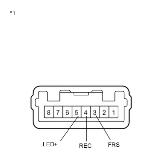
Text in Illustration *1 Component without harness connected
(Heater Control Base [Air Inlet Control Switch])
Disconnect the connector from the heater control base (air inlet control switch).
-
Measure the resistance according to the value(s) in the table below.
Standard Resistance Tester Connection Switch Condition Specified Condition 3 (FRS) - 4 (REC) Air inlet control switch FREE Below 1 Ω 3 (FRS) - 4 (REC) Air inlet control switch LOCK 10 kΩ or higher -
Check that the indicator light comes on.
-
Turn the heater control base (air inlet control switch) to LOCK.
-
Connect the positive (+) lead from the battery to terminal 2 and the negative (-) lead to terminal 4, and check that the indicator light comes on.
OK The indicator light comes on. If the result is not as specified, replace the heater control base (air inlet control switch).
-
-
-
INSPECT HEATER CONTROL (BLOWER SWITCH)
-
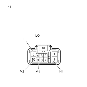
Text in Illustration *1 Component without harness connected
(Heater Control [Blower Switch])
Disconnect the connector from the heater control (blower switch).
-
Measure the resistance according to the value(s) in the table below.
Standard Resistance Tester Connection Switch Condition Specified Condition 4 (LO), 6 (HI), 9 (M1), 10 (M2) - 5 (E) Blower switch OFF 10 kΩ or higher 4 (LO) - 5 (E) Blower switch LO Below 1 Ω 4 (LO), 9 (M1) - 5 (E) Blower switch M1 Below 1 Ω 4 (LO), 10 (M2) - 5 (E) Blower switch M2 Below 1 Ω 4 (LO), 6 (HI) - 5 (E) Blower switch HI Below 1 Ω -
Check that the indicator light comes on.
-
Turn the heater control base (air inlet control switch) to LOCK.
-
Connect the positive (+) lead from the battery to terminal 2 and the negative (-) lead to terminal 4, and check that the indicator light comes on.
OK The indicator light comes on. If the result is not as specified, replace the heater control (blower switch).
-
-
-
INSPECT NO. 3 HEATER CONTROL
-
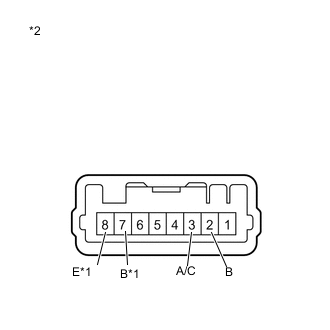
Text in Illustration *1 w/ PTC Heater *2 Component without harness connected
(No. 3 Heater Control)
Disconnect the connector from the No. 3 heater control.
-
Measure the resistance according to the value(s) in the table below.
Standard Resistance Tester Connection Switch Condition Specified Condition 2 (B) - 3 (A/C) No. 3 heater control (A/ C) LOCK Below 1 Ω 2 (B) - 3 (A/C) No. 3 heater control (A/ C) FREE 10 kΩ or higher 7 (B) - 8 (E) *1 No. 3 heater control (MAX HOT) ON Below 1 Ω 7 (B) - 8 (E) *1 No. 3 heater control (MAX HOT) OFF 10 kΩ or higher *1: w/ PTC Heater
-
Check that the indicator light comes on.
-
Connect the positive (+) lead from the battery to terminal 3 and the negative (-) lead to terminal 4, and check that the indicator light comes on.
OK The indicator light comes on. If the result is not as specified, replace the No. 3 heater control.
-
-