AIR CONDITIONING SYSTEM(for Manual Air Conditioning System) PTC Heater Circuit
DESCRIPTION
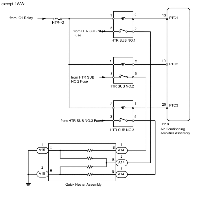
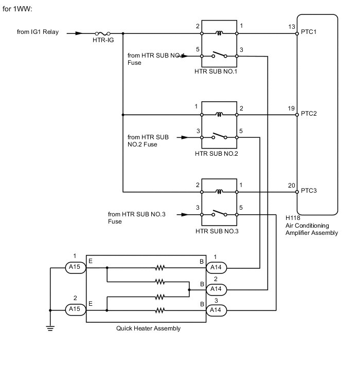
PTC heater relays are closed in accordance with signals from the air conditioning amplifier assembly and power is supplied to the quick heater assembly installed on the radiator heater unit.
WIRING DIAGRAM
PROCEDURE
-
INSPECT PTC HEATER RELAY (HTR SUB NO.1, HTR SUB NO.2, HTR SUB NO.3)
-
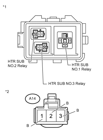
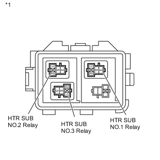
except 1WW:
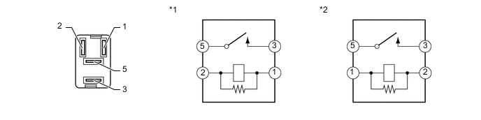
Text in Illustration *1 HTR SUB NO.1 Relay, HTR SUB NO.2 Relay *2 HTR SUB NO.3 Relay
-
Remove the HTR SUB NO.1, HTR SUB NO.2 and HTR SUB NO.3 relays from the engine room No. 2 relay block.
-
Measure the resistance according to the value(s) in the table below.
Standard Resistance Tester Connection Condition Specified Condition 3 - 5 Battery voltage is not applied to terminals 1 and 2 10 kΩ or higher Battery voltage is applied to terminals 1 and 2 Below 1 Ω
-
-
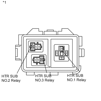
for 1WW:
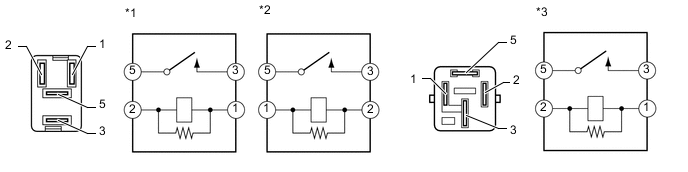
Text in Illustration *1 HTR SUB NO.2 Relay *2 HTR SUB NO.3 Relay *3 HTR SUB NO.1 Relay - -
-
Remove the HTR SUB NO.1, HTR SUB NO.2 and HTR SUB NO.3 relays from the engine room No. 2 relay block.
-
Measure the resistance according to the value(s) in the table below.
Standard Resistance Tester Connection Condition Specified Condition 3 - 5 Battery voltage is not applied to terminals 1 and 2 10 kΩ or higher Battery voltage is applied to terminals 1 and 2 Below 1 Ω
-
NG 
REPLACE PTC HEATER RELAY (HTR SUB NO.1, HTR SUB NO.2, HTR SUB NO.3)
OK 
-
-
CHECK AIR CONDITIONING AMPLIFIER ASSEMBLY
-
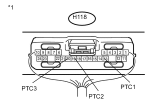
Text in Illustration *1 Component with harness connected
(Air Conditioning Amplifier Assembly)
Remove the air conditioning amplifier assembly with its connectors still connected Click here.
-
Measure the voltage according to the value(s) in the table below.
Standard Voltage Tester Connection Condition Specified Condition H118-13 (PTC1) - Body ground
-
Engine running (1250 rpm or more)
-
Temperature setting MAX HOT
-
Outside temperature 10°C (50°F) or less
-
Engine coolant temperature 75°C (167°F) or less
-
Headlight dimmer switch off
-
Blower switch off
11 to 14 V* H118-19 (PTC2) - Body ground
-
Engine running (1250 rpm or more)
-
Temperature setting MAX HOT
-
Outside temperature 10°C (50°F) or less
-
Engine coolant temperature 70°C (158°F) or less
-
Headlight dimmer switch off
-
Blower switch off
H118-20 (PTC3) - Body ground
-
Engine running (1250 rpm or more)
-
Temperature setting MAX HOT
-
Outside temperature 10°C (50°F) or less
-
Engine coolant temperature 65°C (149°F) or less
-
Headlight dimmer switch off
-
Blower switch off
H118-13 (PTC1) - Body ground
-
Engine running (1250 rpm or more)
-
Temperature setting MAX HOT
-
Outside temperature 10°C (50°F) or less
-
Engine coolant temperature 75°C (167°F) or less
-
Headlight dimmer switch off
-
Blower switch on
Below 1 V* H118-19 (PTC2) - Body ground
-
Engine running (1250 rpm or more)
-
Temperature setting MAX HOT
-
Outside temperature 10°C (50°F) or less
-
Engine coolant temperature 70°C (158°F) or less
-
Headlight dimmer switch off
-
Blower switch on
H118-20 (PTC3) - Body ground
-
Engine running (1250 rpm or more)
-
Temperature setting MAX HOT
-
Outside temperature 10°C (50°F) or less
-
Engine coolant temperature 65°C (149°F) or less
-
Headlight dimmer switch off
-
Blower switch on
Tech Tips
*: After the measurement conditions are met, wait 30 seconds before performing measurements.
-
NG
PROCEED TO NEXT SUSPECTED AREA SHOWN IN PROBLEM SYMPTOMS TABLE Click here
OK
-
-
CHECK HARNESS AND CONNECTOR (PTC HEATER RELAY - AIR CONDITIONING AMPLIFIER)
-
except 1WW:
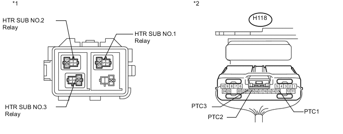
Text in Illustration *1 Component without relay installed
(Engine Room No. 2 Relay Block)
*2 Rear view of wire harness connector
(to Air Conditioning Amplifier)
-
Remove the PTC heater relays from the engine room No. 2 relay block.
-
Disconnect the H118 amplifier connector.
-
Measure the resistance according to the value(s) in the table below.
Standard Resistance Tester Connection Condition Specified Condition HTR SUB NO.1 relay terminal 2 - H118-13 (PTC1) Always Below 1 Ω HTR SUB NO.2 relay terminal 2 - H118-19 (PTC2) HTR SUB NO.3 relay terminal 1 - H118-20 (PTC3) HTR SUB NO.1 relay terminal 2 - Body ground Always 10 kΩ or higher HTR SUB NO.2 relay terminal 2 - Body ground HTR SUB NO.3 relay terminal 1 - Body ground
-
-
for 1WW:
-
Remove the PTC heater relays from the engine room No. 2 relay block.
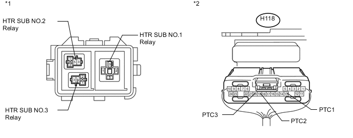
Text in Illustration *1 Component without relay installed
(Engine Room No. 2 Relay Block)
*2 Rear view of wire harness connector
(to Air Conditioning Amplifier)
-
Disconnect the H118 amplifier connector.
-
Measure the resistance according to the value(s) in the table below.
Standard Resistance Tester Connection Condition Specified Condition HTR SUB NO.1 relay terminal 1 - H118-13 (PTC1) Always Below 1 Ω HTR SUB NO.2 relay terminal 2 - H118-19 (PTC2) HTR SUB NO.3 relay terminal 1 - H118-20 (PTC3) HTR SUB NO.1 relay terminal 1 - Body ground Always 10 kΩ or higher HTR SUB NO.2 relay terminal 2 - Body ground HTR SUB NO.3 relay terminal 1 - Body ground
-
NG
REPAIR OR REPLACE HARNESS OR CONNECTOR
OK
-
-
CHECK HARNESS AND CONNECTOR (PTC HEATER RELAY - QUICK HEATER)
-
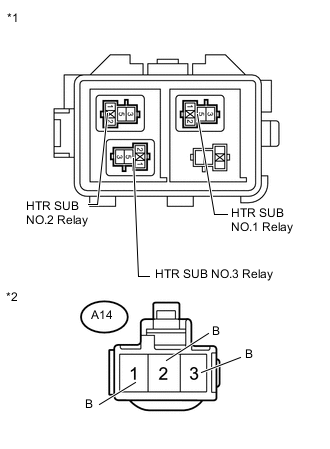
Text in Illustration *1 Component without relay installed
(Engine Room No. 2 Relay Block)
*2 Front view of wire harness connector
(to Quick Heater Assembly)
except 1WW:
-
Remove the PTC heater relays from the engine room No. 2 relay block.
-
Disconnect the A14 heater connector.
-
Measure the resistance according to the value(s) in the table below.
Standard Resistance Tester Connection Condition Specified Condition HTR SUB NO.1 relay terminal 5 - A14-1 (B) Always Below 1 Ω HTR SUB NO.2 relay terminal 5 - A14-2 (B) HTR SUB NO.3 relay terminal 5 - A14-3 (B) HTR SUB NO.1 relay terminal 5 - Body ground Always 10 kΩ or higher HTR SUB NO.2 relay terminal 5 - Body ground HTR SUB NO.3 relay terminal 5 - Body ground
-
-
Text in Illustration *1 Component without relay installed
(Engine Room No. 2 Relay Block)
*2 Front view of wire harness connector
(to Quick Heater Assembly)
for 1WW:
-
Remove the PTC heater relays from the engine room No. 2 relay block.
-
Disconnect the A14 heater connector.
-
Measure the resistance according to the value(s) in the table below.
Standard Resistance Tester Connection Condition Specified Condition HTR SUB NO.1 relay terminal 3 - A14-2 (B) Always Below 1 Ω HTR SUB NO.2 relay terminal 5 - A14-1 (B) HTR SUB NO.3 relay terminal 5 - A14-3 (B) HTR SUB NO.1 relay terminal 3 - Body ground Always 10 kΩ or higher HTR SUB NO.2 relay terminal 5 - Body ground HTR SUB NO.3 relay terminal 5 - Body ground
-
NG
REPAIR OR REPLACE HARNESS OR CONNECTOR
OK
-
-
CHECK HARNESS AND CONNECTOR (PTC HEATER RELAY - BATTERY AND BODY GROUND)
-
Text in Illustration *1 Component without relay installed
(Engine Room No. 2 Relay Block)
except 1WW:
-
Remove the PTC heater relays from the engine room No. 2 relay block.
-
Measure the voltage according to the value(s) in the table below.
Standard Voltage Tester Connection Condition Specified Condition HTR SUB NO.1 relay terminal 3 - Body ground Always 11 to 14 V HTR SUB NO.2 relay terminal 3 - Body ground HTR SUB NO.3 relay terminal 3 - Body ground -
Measure the resistance according to the value(s) in the table below.
Standard Resistance Tester Connection Condition Specified Condition HTR SUB NO.1 relay terminal 1 - Body ground Always Below 1 Ω HTR SUB NO.2 relay terminal 1 - Body ground HTR SUB NO.3 relay terminal 2 - Body ground
-
-
Text in Illustration *1 Component without relay installed
(Engine Room No. 2 Relay Block)
for 1WW:
-
Remove the PTC heater relays from the engine room No. 2 relay block.
-
Measure the voltage according to the value(s) in the table below.
Standard Voltage Tester Connection Condition Specified Condition HTR SUB NO.1 relay terminal 5 - Body ground Always 11 to 14 V HTR SUB NO.2 relay terminal 3 - Body ground HTR SUB NO.3 relay terminal 3 - Body ground -
Measure the resistance according to the value(s) in the table below.
Standard Resistance Tester Connection Condition Specified Condition HTR SUB NO.1 relay terminal 2 - Body ground Always Below 1 Ω HTR SUB NO.2 relay terminal 1 - Body ground HTR SUB NO.3 relay terminal 2 - Body ground
-
NG
REPAIR OR REPLACE HARNESS OR CONNECTOR
OK
-
-
INSPECT QUICK HEATER ASSEMBLY
-
Remove the quick heater assembly connectors Click here.
-
Measure the resistance according to the value(s) in the table below.
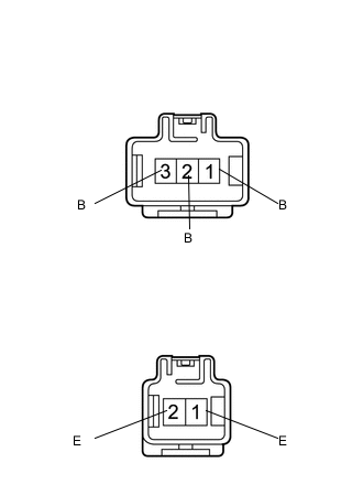
Standard Resistance Tester Connection Condition Specified Condition 1 (B) - 1 (E) Always Below 1 kΩ 2 (B) - 1 (E) 2 (B) - 2 (E) 3 (B) - 2 (E)
NG
REPLACE QUICK HEATER ASSEMBLY Click here
OK
-
-
CHECK HARNESS AND CONNECTOR (QUICK HEATER - BODY GROUND)
-
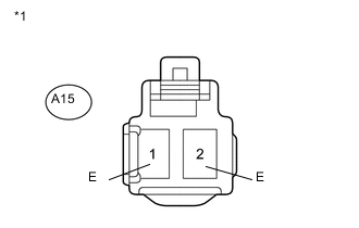
Text in Illustration *1 Front view of wire harness connector
(to Quick Heater Assembly)
Disconnect the A15 heater connector.
-
Measure the resistance according to the value(s) in the table below.
Standard Resistance Tester Connection Condition Specified Condition A15-1 (E) - Body ground Always Below 1 Ω A15-2 (E) - Body ground
OK
PROCEED TO NEXT SUSPECTED AREA SHOWN IN PROBLEM SYMPTOMS TABLE Click here
NG
REPAIR OR REPLACE HARNESS OR CONNECTOR
-