AIR CONDITIONING SYSTEM(for Manual Air Conditioning System), Diagnostic DTC:B1451
| DTC Code | DTC Name |
|---|---|
| B1451 | Compressor Solenoid Circuit |
DESCRIPTION
In this circuit, the compressor assembly with pulley receives a refrigerant compression demand signal from the air conditioning amplifier assembly. Based on this signal, the compressor assembly with pulley changes the degree of refrigerant compression.
| DTC Code | DTC Detection Condition | Trouble Area |
|---|---|---|
| B1451 | Open or short in the externally changeable compressor assembly with pulley solenoid circuit. |
|
WIRING DIAGRAM
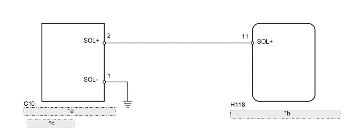
| *a | Compressor Assembly with Pulley |
| *b | Air Conditioning Amplifier Assembly |
| *c | - Solenoid Valve |
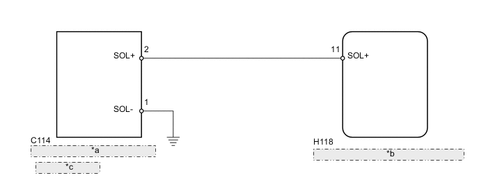
| *a | Compressor Assembly with Pulley |
| *b | Air Conditioning Amplifier Assembly |
| *c | - Solenoid Valve |
PROCEDURE
-
READ VALUE USING INTELLIGENT TESTER
-
Use the Data List to check if the compressor assembly with pulley is functioning properly.
Air Conditioner Tester Display Measurement Item/Range Normal Condition Diagnostic Note Regulator Control Current Compressor assembly with pulley / Min.: 0, Max.: 0.997 Value changes between 0 A and 0.997 A in accordance with compressor assembly with pulley operation - OK The display is as specified in the normal condition column. Result Result Proceed to OK (When troubleshooting according to Problem Symptoms Table) A OK (When troubleshooting according to the DTC) B NG C
A 
PROCEED TO NEXT SUSPECTED AREA SHOWN IN PROBLEM SYMPTOMS TABLE Click here
B
REPLACE AIR CONDITIONING AMPLIFIER ASSEMBLY Click here
C 
-
-
INSPECT COMPRESSOR ASSEMBLY WITH PULLEY
-
except 1WW:
Remove the compressor assembly with pulley Click here.
-
for 1WW:
Remove the compressor assembly with pulley Click here.
-
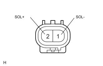
Measure the resistance according to the value(s) in the table below.
Standard Resistance Tester Connection Condition Specified Condition 2 (SOL+) - 1 (SOL-) 20°C (68°F) 10 to 11 Ω Result Result Proceed to OK A NG (except 1WW) B NG (for 1WW) C
B
REPLACE COMPRESSOR ASSEMBLY WITH PULLEY Click here
C
REPLACE COMPRESSOR ASSEMBLY WITH PULLEY Click here
A
-
-
CHECK HARNESS AND CONNECTOR (COMPRESSOR - BODY GROUND)
-
except 1WW:
-
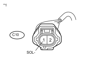
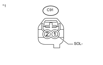
Text in Illustration *1 Front view of wire harness connector
(to Compressor Assembly with Pulley)
Disconnect the C10 compressor connector.
-
Measure the resistance according to the value(s) in the table below.
Standard Resistance Tester Connection Condition Specified Condition C10-1 (SOL-) - Body ground Always Below 1 Ω
-
-
for 1WW:
-
Text in Illustration *1 Front view of wire harness connector
(to Compressor Assembly with Pulley)
Disconnect the C114 compressor connector.
-
Measure the resistance according to the value(s) in the table below.
Standard Resistance Tester Connection Condition Specified Condition C114-1 (SOL-) - Body ground Always Below 1 Ω
-
NG
REPAIR OR REPLACE HARNESS OR CONNECTOR
OK
-
-
CHECK HARNESS AND CONNECTOR (COMPRESSOR - AIR CONDITIONING AMPLIFIER)
-
except 1WW:
-
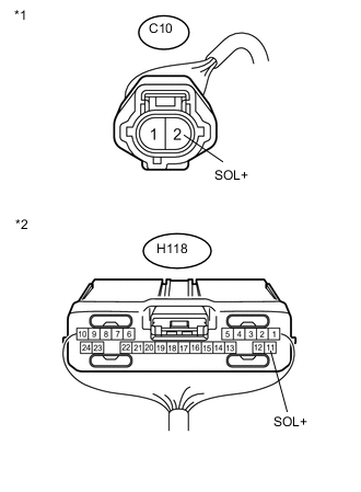
Text in Illustration *1 Front view of wire harness connector
(to Compressor Assembly with Pulley)
*2 Rear view of wire harness connector
(to Air Conditioning Amplifier Assembly)
Disconnect the C10 compressor connector.
-
Disconnect the H9 amplifier connector.
-
Measure the resistance according to the value(s) in the table below.
Standard Resistance Tester Connection Condition Specified Condition H118-11 (SOL+) - C10-2 (SOL+) Always Below 1 Ω H118-11 (SOL+) - Body ground Always 10 kΩ or higher
-
-
for 1WW:
-
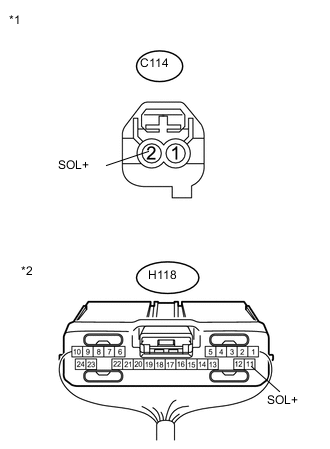
Text in Illustration *1 Front view of wire harness connector
(to Compressor Assembly with Pulley)
*2 Rear view of wire harness connector
(to Air Conditioning Amplifier Assembly)
Disconnect the C114 compressor connector.
-
Disconnect the H118 amplifier connector.
-
Measure the resistance according to the value(s) in the table below.
Standard Resistance Tester Connection Condition Specified Condition H118-11 (SOL+) - C114-2 (SOL+) Always Below 1 Ω H118-11 (SOL+) - Body ground Always 10 kΩ or higher
-
OK
REPLACE AIR CONDITIONING AMPLIFIER ASSEMBLY Click here
NG
REPAIR OR REPLACE HARNESS OR CONNECTOR
-