AIR CONDITIONING SYSTEM(for Manual Air Conditioning System) SYSTEM DESCRIPTION
-
GENERAL
-
The air conditioning system has the following controls.
Control Outline Variable Capacity Compressor Control Controls the compressor to turn on or off to control the discharge capacity based on the signals from various sensors. Diagnosis A Diagnostic Trouble Code (DTC) is stored in memory when the air conditioning amplifier detects a problem with the air conditioning system.
-
-
MODE POSITION AND DAMPER OPERATION
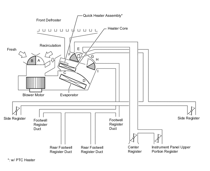
Function of Main Damper Control Damper Operation Position Damper Position Operation Air Inlet Control Damper Fresh A Brings in fresh air. Recirculation B Recirculates internal air. Air Mix Control Damper MAX COOL to MAX HOT C - D Varies the mixture of cold air and hot air in order to regulate the temperature continuously from hot to cool. Mode Control Damper 
Face
F, I Air blows out of the center registers, instrument panel upper portion register, and side registers. 
Bi-level
F, H Air blows out of the center registers, instrument panel upper portion register, side registers, and front and rear footwell register ducts. 
Foot
E, G Air blows out of the front and rear footwell register ducts and side registers.
In addition, air blows out slightly from the front defroster.

Foot/Def
E, H Defrosts the windshield through the front defroster and side registers, while air is also blown out from the front and rear footwell register ducts. 
Def
E, I Defrosts the windshield through the front defroster and side registers. -
AIR OUTLETS AND AIRFLOW VOLUME
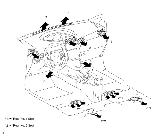
INDICATION
(MODE)
Center Register Side Register Front and Rear Footwell Register Defroster A B C D Face

- - Bi-level

- Foot
- 

Foot/Def
- Def
- - Tech Tips
-
The size of the circle indicates the proportion of airflow volume.
-
The same system is used for LHD and RHD vehicles.
-
-
COMPRESSOR ASSEMBLY WITH PULLEY
-
General:
-
The compressor assembly with pulley is a continuously variable capacity type in which its capacity can be varied in accordance with the cooling load of the air conditioning system.
-
The compressor assembly with pulley consists of the A/C pulley, shaft, lug plate, swash plate, piston, shoe, crank chamber, cylinder and solenoid valve.
-
The solenoid valve enables control of the suction pressure.
-
The internal valve improves the durability of the A/C compressor assembly with pulley under high speed and large thermal load conditions. The internal valve is integrated into the solenoid valve.
-
-
Solenoid Valve Operation:
-
The crank chamber is connected to the suction passage. The solenoid valve is located between the suction passage (low pressure) and discharge passage (high pressure).
-
The solenoid valve operates under duty cycle control in accordance with the signals from the air conditioning amplifier assembly.
-
When the solenoid valve closes (solenoid coil is energized), a difference in pressure is created and the pressure in the crank chamber decreases. Then, the pressure that is applied to the right side of the piston becomes higher than the pressure that is applied to the left side of the piston. This compresses the spring and tilts the swash plate. As a result, the piston stroke increases and the discharge capacity also increases.
-
When the solenoid valve opens (solenoid coil is not energized), the difference in pressure disappears. Then, the pressure that is applied to the left side of the piston becomes the same as the pressure that is applied to the right side of the piston. Thus, the spring elongates and eliminates the tilt of the swash plate. As a result, there is no piston stroke and the discharge capacity is reduced.
-
-
Internal Valve Operation:
-
The internal valve operates when the speed of the compressor assembly with pulley has increased rapidly, the speed of the compressor assembly with pulley is high, or when the thermal load has suddenly changed. As a result, the capacity of the compressor assembly with pulley is reduced and the durability of the compressor assembly with pulley increases.
-
-
-
NO. 1 COOLER THERMISTOR
The No. 1 cooler thermistor detects the temperature of the cool air immediately after it passes through the evaporator in the form of resistance changes, and outputs the temperature to the air conditioning amplifier assembly.
-
QUICK HEATER ASSEMBLY (w/ PTC HEATER)
-
General
-
The PTC heater is located above the heater core in the air conditioner unit.
-
The PTC heater consists of a PTC element, aluminum fins, and brass plates. When current is applied to the PTC element, it generates heat to warm the air that passes through the unit.
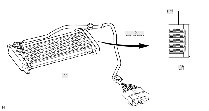
*1 Brass Plate *2 PTC Element *3 Aluminum Fin *4 Quick Heater Assembly (PTC Heater)
-
-
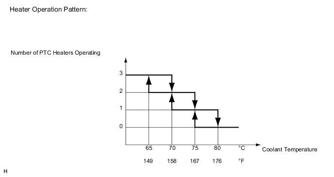
PTC Heater Operating Conditions
-
The on/off operation of the PTC heater is controlled by the air conditioning amplifier in accordance with the coolant temperature, ambient temperature, engine speed, air mix setting and electrical load (generator power ratio).
For example, the number of operating PTC heaters varies according to coolant temperature as shown in the graph below.
-
-
-
COOLER THERMISTOR (AMBIENT TEMPERATURE SENSOR)
The cooler thermistor (ambient temperature sensor) detects the outside temperature based on changes in the resistance of its built-in thermistor and sends a signal to the air conditioning amplifier assembly.
-
AIR CONDITIONING PRESSURE SENSOR
The air conditioning pressure sensor detects the refrigerant pressure and outputs the pressure to the air conditioning amplifier assembly in the form of voltage changes.