SEAT BELT WARNING SYSTEM Rear Seat Belt Warning Light Malfunction
DESCRIPTION
When a rear door is opened and closed (the rear door courtesy light switch turns on and off) with the ignition switch ON, or when a rear door is opened and closed (the rear door courtesy light switch turns on and off) and then the ignition switch is turned to ON, the rear seat belt warning light in the telltale light assembly turns on to inform the driver of condition of the rear seat belts. If a rear seat belt is fastened or unfastened, the warning light changes to indicate the current condition of the rear seat belts.
-
This is only for vehicles with a rear No. 1 seat or vehicles with a rear No. 1 and rear No. 2 seat.
WIRING DIAGRAM
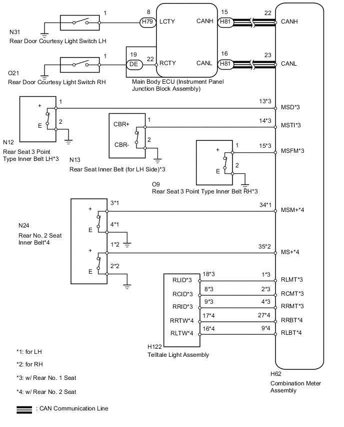
PROCEDURE
-
CHECK FOR DTC (CAN COMMUNICATION SYSTEM)
-
Check if a CAN communication system DTC is output.
Result Result Proceed to DTC is not output A CAN communication system DTC is output B
B 
GO TO CAN COMMUNICATION SYSTEM Click here
A 
-
-
READ VALUE USING INTELLIGENT TESTER (REAR DOOR COURTESY LIGHT SWITCH)
-
Check the Data List for proper functioning of the rear door courtesy light switch Click here.
Main Body Tester Display Measurement Item/Range Normal Condition Diagnostic Note RL Door Courtesy SW Rear door LH courtesy light switch signal / ON or OFF ON: Rear door LH open
OFF: Rear door LH closed
- RR Door Courtesy SW Rear door RH courtesy light switch signal / ON or OFF ON: Rear door RH open
OFF: Rear door RH closed
- OK The display is as specified in the normal condition column.
NG 
INSPECT REAR DOOR COURTESY LIGHT SWITCH ASSEMBLY Click here
OK
-
-
READ VALUE USING INTELLIGENT TESTER (REAR SEAT BELT BUCKLE SWITCH)
-
Check the Data List for proper functioning of the rear seat belt buckle switch Click here.
Combination Meter Tester Display Measurement Item/Range Normal Condition Diagnostic Note 2nd-Row Seatbelt Buckle (R)*1 Rear No. 1 seat belt buckle RH signal / ON or OFF ON: Rear No. 1 seat belt RH fastened
OFF: Rear No. 1 seat belt RH unfastened
- 2nd-Row Seatbelt Buckle (L)*1 Rear No. 1 seat belt buckle LH signal / ON or OFF ON: Rear No. 1 seat belt LH fastened
OFF: Rear No. 1 seat belt LH unfastened
- 2nd-Row Seatbelt Buckle (C)*1 Rear No. 1 seat center belt buckle signal / ON or OFF ON: Rear No. 1 seat center belt fastened
OFF: Rear No. 1 seat center belt unfastened
- 3rd-Row Seatbelt Buckle (R)*2 Rear No. 2 seat belt buckle RH signal / ON or OFF ON: Rear No. 2 seat belt RH fastened
OFF: Rear No. 2 seat belt RH unfastened
- 3rd-Row Seatbelt Buckle (L)*2 Rear No. 2 seat belt buckle LH signal / ON or OFF ON: Rear No. 2 seat belt LH fastened
OFF: Rear No. 2 seat belt LH unfastened
-
-
*1: w/ Rear No. 1 Seat
-
*2: w/ Rear No. 2 Seat
OK The display is as specified in the normal condition column. Result Result Proceed to OK A NG (w/o Rear No. 2 Seat) B NG (w/ Rear No. 2 Seat) C -
B
INSPECT REAR SEAT INNER BELT Click here
C
INSPECT REAR NO. 2 SEAT INNER BELT ASSEMBLY Click here
A
-
-
CHECK HARNESS AND CONNECTOR (COMBINATION METER ASSEMBLY - TELLTALE LIGHT ASSEMBLY)
-
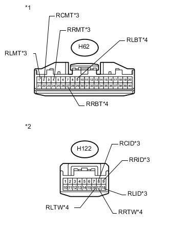
Text in Illustration *1 Front view of wire harness connector
(to Combination Meter Assembly)
*2 Front view of wire harness connector
(to Telltale Light Assembly)
*3 w/ Rear No. 1 Seat *4 w/ Rear No. 2 Seat Disconnect the H62 combination meter assembly connector.
-
Disconnect the H122 telltale light assembly connector.
-
Measure the resistance according to the value(s) in the table below.
Standard Resistance Tester Connection Condition Specified Condition H62-1 (RLMT) - H122-18 (RLID)*1 Always Below 1 Ω H62-2 (RCMT) - H122-8 (RCID)*1 H62-4 (RRMT) - H122-9 (RRID)*1 H62-27 (RRBT) - H122-17 (RRTW)*2 H62-9 (RLBT) - H122-16 (RLTW)*2 H62-1 (RLMT) - Body ground*1 Always 10 kΩ or higher H62-2 (RCMT) - Body ground*1 H62-4 (RRMT) - Body ground*1 H62-27 (RRBT) - Body ground*2 H62-9 (RLBT) - Body ground*2
-
*1: w/ Rear No. 1 Seat
-
*2: w/ Rear No. 2 Seat
-
NG
REPAIR OR REPLACE HARNESS OR CONNECTOR
OK
-
-
CHECK TELLTALE LIGHT ASSEMBLY
-
Replace the telltale light assembly with a new or normally functioning one Click here.
-
Check that the operation of the telltale light assembly returns to normal.
OK The operation of the telltale light assembly returns to normal.
OK
END (TELLTALE LIGHT ASSEMBLY WAS DEFECTIVE)
NG
REPLACE COMBINATION METER ASSEMBLY Click here
-
-
INSPECT REAR DOOR COURTESY LIGHT SWITCH ASSEMBLY
-
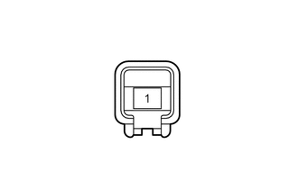
Remove the rear door courtesy light switch Click here.
-
Measure the resistance according to the value(s) in the table below.
Standard Resistance Tester Connection Condition Specified Condition 1 - Body ground Switch not pushed Below 1 Ω Switch pushed 10 kΩ or higher
NG
REPLACE REAR DOOR COURTESY LIGHT SWITCH ASSEMBLY Click here
OK
-
-
CHECK HARNESS AND CONNECTOR (REAR DOOR COURTESY LIGHT SWITCH - MAIN BODY ECU [INSTRUMENT PANEL JUNCTION BLOCK ASSEMBLY])
-
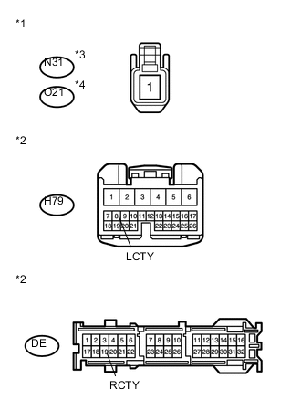
Text in Illustration *1 Front view of wire harness connector
(to Rear Door Courtesy Light Switch)
*2 Front view of wire harness connector
(to Main Body ECU [Instrument Panel Junction Block Assembly])
*3 for LH *4 for RH for LH:
-
Disconnect the N31 rear door courtesy light switch LH connector.
-
Disconnect the H79 main body ECU (instrument panel junction block assembly) connector.
-
Measure the resistance according to the value(s) in the table below.
Standard Resistance Tester Connection Condition Specified Condition N31-1 - H79-8 (LCTY) Always Below 1 Ω
-
-
for RH:
-
Disconnect the O21 rear door courtesy light switch RH connector.
-
Disconnect the DE main body ECU (instrument panel junction block assembly) connector.
-
Measure the resistance according to the value(s) in the table below.
Standard Resistance Tester Connection Condition Specified Condition O21-1 - DE-19 (RCTY) Always Below 1 Ω
-
OK
REPLACE MAIN BODY ECU (INSTRUMENT PANEL JUNCTION BLOCK ASSEMBLY)
NG
REPAIR OR REPLACE HARNESS OR CONNECTOR
-
-
INSPECT REAR SEAT INNER BELT
-
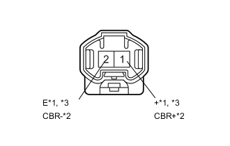
Text in Illustration *1 for LH *2 for Center *3 for RH for LH, RH:
Remove the rear No. 1 seat inner belt Click here.
-
for Center:
Remove the rear seat inner belt (for LH side) Click here.
-
Measure the resistance according to the value(s) in the table below.
Standard Resistance for LH Tester Connection Condition Specified Condition 1 (+) - 2 (E) Rear No. 1 seat belt LH fastened 10 kΩ or higher Rear No. 1 seat belt LH unfastened Below 1 Ω for Center Tester Connection Condition Specified Condition 1 (CBR+) - 2 (CBR-) Rear No. 1 seat center belt fastened 10 kΩ or higher Rear No. 1 seat center belt unfastened Below 1 Ω for RH Tester Connection Condition Specified Condition 1 (+) - 2 (E) Rear No. 1 seat belt RH fastened 10 kΩ or higher Rear No. 1 seat belt RH unfastened Below 1 Ω Result Result Proceed to OK A NG (for LH) B NG (for Center) C NG (for RH) D
B
REPLACE REAR SEAT 3 POINT TYPE INNER BELT ASSEMBLY LH Click here
C
REPLACE REAR SEAT INNER BELT ASSEMBLY (for LH Side) Click here
D
REPLACE REAR SEAT 3 POINT TYPE INNER BELT ASSEMBLY RH Click here
A
-
-
CHECK HARNESS AND CONNECTOR (REAR SEAT INNER BELT - COMBINATION METER ASSEMBLY AND BODY GROUND)
-
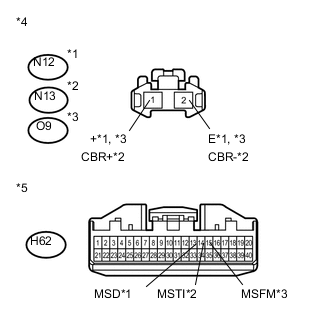
Text in Illustration *1 for LH *2 for Center *3 for RH *4 Front view of wire harness connector
(to Rear No. 1 Seat Inner Belt)
*5 Front view of wire harness connector
(to Combination Meter Assembly)
Disconnect the N12*1, N13*2 or O9*3 rear No. 1 seat inner belt connector.
-
*1: for LH
-
*2: for Center
-
*3: for RH
-
-
Disconnect the H62 combination meter assembly connector.
-
Measure the resistance according to the value(s) in the table below.
Standard Resistance for LH Tester Connection Condition Specified Condition N12-1 (+) - H62-13 (MSD) Always Below 1 Ω N12-2 (E) - Body ground N12-1 (+) - Body ground Always 10 kΩ or higher for Center Tester Connection Condition Specified Condition N13-1 (CBR+) - H62-14 (MSTI) Always Below 1 Ω N13-2 (CBR-) - Body ground N13-1 (CBR+) - Body ground Always 10 kΩ or higher for RH Tester Connection Condition Specified Condition O9-1 (+) - H62-15 (MSFM) Always Below 1 Ω O9-2 (E) - Body ground O9-1 (+) - Body ground Always 10 kΩ or higher
OK
REPLACE COMBINATION METER ASSEMBLY Click here
NG
REPAIR OR REPLACE HARNESS OR CONNECTOR
-
-
INSPECT REAR NO. 2 SEAT INNER BELT ASSEMBLY
-
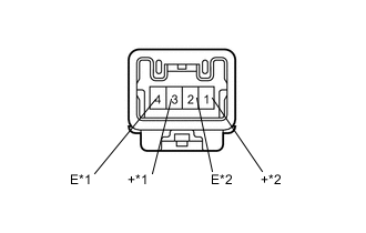
Text in Illustration *1 for LH *2 for RH Remove the rear No. 2 seat inner belt Click here.
-
Measure the resistance according to the value(s) in the table below.
Standard Resistance for LH Tester Connection Condition Specified Condition 3 (+) - 4 (E) Rear No. 2 seat belt LH fastened 10 kΩ or higher Rear No. 2 seat belt LH unfastened Below 1 Ω for RH Tester Connection Condition Specified Condition 1 (+) - 2 (E) Rear No. 2 seat belt RH fastened 10 kΩ or higher Rear No. 2 seat belt RH unfastened Below 1 Ω
NG
REPLACE REAR NO. 2 SEAT INNER BELT ASSEMBLY Click here
OK
-
-
CHECK HARNESS AND CONNECTOR (REAR NO. 2 SEAT INNER BELT - COMBINATION METER ASSEMBLY AND BODY GROUND)
-
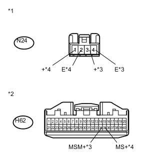
Text in Illustration *1 Front view of wire harness connector
(to Rear No. 2 Seat Inner Belt)
*2 Front view of wire harness connector
(to Combination Meter Assembly)
*3 for LH *4 for RH Disconnect the N24 rear No. 2 seat inner belt connector.
-
Disconnect the H62 combination meter assembly connector.
-
Measure the resistance according to the value(s) in the table below.
Standard Resistance for LH Tester Connection Condition Specified Condition N24-3 (+) - H62-34 (MSM+) Always Below 1 Ω N24-4 (E) - Body ground N24-3 (+) - Body ground Always 10 kΩ or higher for RH Tester Connection Condition Specified Condition N24-1 (+) - H62-35 (MS+) Always Below 1 Ω N24-2 (E) - Body ground N24-1 (+) - Body ground Always 10 kΩ or higher
OK
REPLACE COMBINATION METER ASSEMBLY Click here
NG
REPAIR OR REPLACE HARNESS OR CONNECTOR
-