AIR CONDITIONING SYSTEM(for Automatic Air Conditioning System) SYSTEM DESCRIPTION
-
GENERAL
-
The air conditioning system has the following controls.
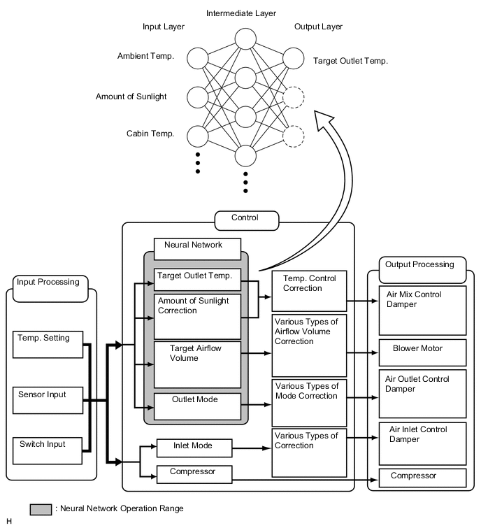
Control Outline Neural Network Control This control is capable of performing complex control by artificially simulating the information processing method of the nervous system of living organisms in order to establish a complex input/output relationship similar to that of a human brain. Outlet Air Temperature Control Based on the temperature set by the temperature control dial, the neural network control calculates outlet air temperature based on input signals from various sensors. Left and Right Independent Control The temperature settings for the driver and front passenger are controlled independently in order to provide separate vehicle interior temperatures for the right and left sides of the vehicle. Blower Control Controls the blower motor in accordance with the airflow volume that has been calculated by the neural network control based on the input signals from various sensors. Air Outlet Control Automatically switches the air outlets in accordance with the outlet mode that has been calculated by the neural network control. In accordance with the engine coolant temperature, ambient air temperature, amount of sunlight, required blower speed, outlet temperature and vehicle speed conditions, this control automatically switches the blower outlet to foot and defroster mode to prevent the windows from becoming fogged up when the ambient air temperature is low. Air Inlet Control Automatically controls the air inlet control damper to help achieve the calculated outlet air temperature that is required. Drives the air inlet control servo motor according to the operation of the air inlet control switch and moves the dampers to the fresh or recirculation position. Compressor Control Through the calculation of the target evaporator temperature based on various sensor signals, the air conditioning amplifier optimally controls discharge capacity by regulating the opening amount of the compressor solenoid valve. Defroster Control Defroster control logic is used to improve defroster performance. Rear Defogger Control When the ignition switch is ON and the rear defogger switch is pushed, the system is activated to keep the defogger heater on for approx. 15 minutes. However, the operating time of the rear defogger can be extended up to approx. 60 minutes when both of the following requirements are met:
-
Ambient Temperature: 0°C (32°F) or less
-
Vehicle Speed: 37.3 mph (60 km/h) or more
Diagnosis A Diagnostic Trouble Code (DTC) is stored in memory when the air conditioning amplifier detects a problem with the air conditioning system. -
-
-
NEURAL NETWORK CONTROL
-
Neural network control collects data under varying environmental conditions and stores it in the air conditioning amplifier assembly. Neural network control uses this data to enhance air conditioning control.
-
The neural network control consists of neurons organized into an input layer, intermediate layer and output layer. The input layer neurons process the input data received from the switches and sensors, which includes the outside temperature, amount of sunlight and room temperature, and outputs this data to the intermediate layer neurons. Based on this data, the intermediate layer neurons adjust the strength of the links among the neurons. The result is then calculated by the output layer neurons in the form of the required outlet temperature, solar correction, target airflow volume and outlet mode control volume. The air conditioning amplifier assembly then controls the servo motors and blower motor in accordance with the control volumes that have been calculated by the neural network control.
-
-
MODE POSITION AND DAMPER OPERATION
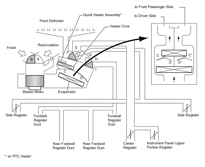
Function of Main Damper Control Damper Operation Position Damper Position Operation Air Inlet Control Damper Fresh A Brings in fresh air. Recirculation B Recirculates internal air. Air Mix Control Damper MAX COOL to MAX HOT C - D
C' - D'
Varies the mixture of cold air and hot air in order to regulate the temperature continuously from hot to cool. Mode Control Damper 
Face
F, I Air blows out of the center registers, instrument panel upper portion register, and side registers. 
Bi-level
F, H Air blows out of the center registers, instrument panel upper portion register, side registers, and front and rear footwell register ducts. 
Foot
E, G Air blows out of the front and rear footwell register ducts and side registers.
In addition, air blows out slightly from the front defroster.

Foot/Def
E, H Defrosts the windshield through the front defroster and side registers, while air is also blown out from the front and rear footwell register ducts. 
Def
E, I Defrosts the windshield through the front defroster and side registers. -
AIR OUTLETS AND AIRFLOW VOLUME
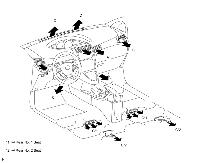
INDICATION
(MODE)
Center Register Side Register Front and Rear Footwell Register Defroster A B C D Face

- - Bi-level

- Foot
- 

Foot/Def
- Def
- - Tech Tips
-
The size of the circle indicates the proportion of airflow volume.
-
The same system is used for LHD and RHD vehicles.
-
-
COMPRESSOR ASSEMBLY WITH PULLEY
-
General:
-
The compressor assembly with pulley is a continuously variable capacity type in which its capacity can be varied in accordance with the cooling load of the air conditioning system.
-
The compressor assembly with pulley consists of the A/C pulley, shaft, lug plate, swash plate, piston, shoe, crank chamber, cylinder and solenoid valve.
-
The solenoid valve enables control of the suction pressure.
-
The internal valve improves the durability of the compressor assembly with pulley under high speed and large thermal load conditions. The internal valve is integrated into the solenoid valve.
-
-
Solenoid Valve Operation:
-
The crank chamber is connected to the suction passage. The solenoid valve is located between the suction passage (low pressure) and discharge passage (high pressure).
-
The solenoid valve operates under duty cycle control in accordance with the signals from the air conditioning amplifier assembly.
-
When the solenoid valve closes (solenoid coil is energized), a difference in pressure is created and the pressure in the crank chamber decreases. Then, the pressure that is applied to the right side of the piston becomes higher than the pressure that is applied to the left side of the piston. This compresses the spring and tilts the swash plate. As a result, the piston stroke increases and the discharge capacity also increases.
-
When the solenoid valve opens (solenoid coil is not energized), the difference in pressure disappears. Then, the pressure that is applied to the left side of the piston becomes the same as the pressure that is applied to the right side of the piston. Thus, the spring elongates and eliminates the tilt of the swash plate. As a result, there is no piston stroke and the discharge capacity is reduced.
-
-
Internal Valve Operation:
-
The internal valve operates when the speed of the compressor assembly with pulley has increased rapidly, the speed of the compressor assembly with pulley is high, or when the thermal load has suddenly changed. As a result, the capacity of the compressor assembly with pulley is reduced and the durability of the compressor assembly with pulley increases.
-
-
-
NO. 1 COOLER THERMISTOR
The No. 1 cooler thermistor detects the temperature of the cool air immediately after it passes through the evaporator in the form of resistance changes, and outputs the temperature to the air conditioning amplifier assembly.
-
BLOWER WITH FAN MOTOR SUB-ASSEMBLY
The blower with fan motor sub-assembly has a built-in blower controller, and is controlled by the air conditioning amplifier assembly using duty control.
-
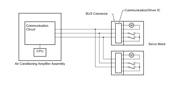
AIR CONDITIONING HARNESS ASSEMBLY (BUS CONNECTOR)
-
A BUS connector is used in the wire harness that connects the servo motor to the air conditioning amplifier assembly.
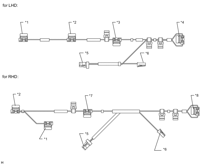
Connector Type Connected to *1: Bus connector Damper servo sub-assembly *2: Bus connector Air outlet control servo motor *3: Bus connector Air mix control servo motor RH (for front passenger side) *4: Bus connector Air mix control servo motor LH (for driver side) *5: Connector Air conditioning amplifier assembly *6: Connector No. 1 cooler thermistor *7: Bus connector Air mix control servo motor RH (for driver side) *8: Bus connector Air mix control servo motor LH (for front passenger side) -
Each BUS connector has a built-in communication/driver IC which communicates with each servo motor connector, actuates the servo motor, and has a position detection function.
-
-
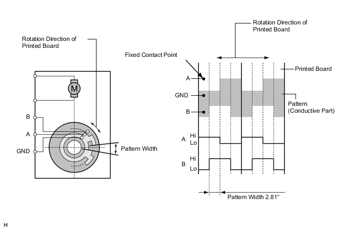
SERVO MOTOR
-
The pulse pattern type servo motor detects the relative position using 2-bit on/off signals.
The forward and reverse revolutions of this motor are detected using two signals, A and B, which output four types of patterns. The air conditioning amplifier counts the number of pulse patterns in order to determine the stopped position.
-
-
QUICK HEATER ASSEMBLY (w/ PTC Heater)
-
General
-
The PTC heater is located above the heater core in the air conditioner unit.
-
The PTC heater consists of a PTC element, aluminum fins, and brass plates. When current is applied to the PTC element, it generates heat to warm the air that passes through the unit.
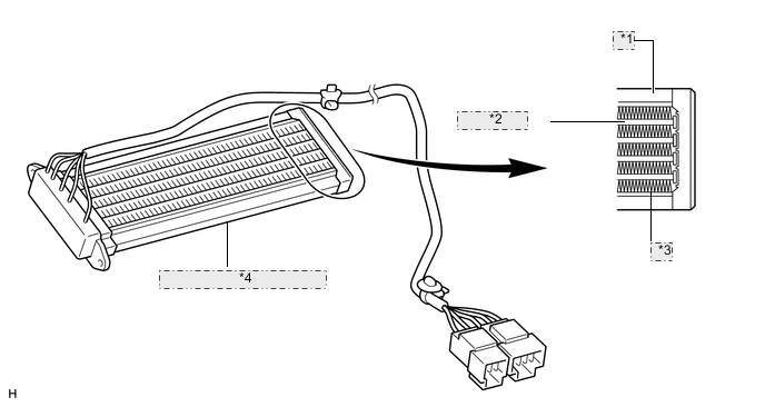
*1 Brass Plate *2 PTC Element *3 Aluminum Fin *4 Quick Heater Assembly (PTC Heater)
-
-
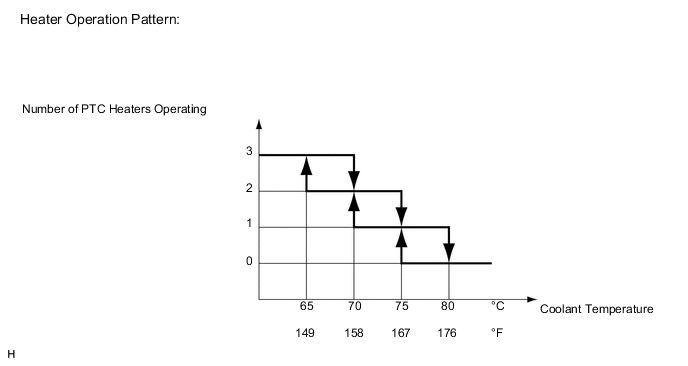
PTC Heater Operating Conditions
-
The on/off operation of the PTC heater is controlled by the air conditioning amplifier in accordance with the coolant temperature, ambient temperature, engine speed, air mix setting and electrical load (generator power ratio).
For example, the number of operating PTC heaters varies according to coolant temperature as shown in the graph below.
-
-
-
COOLER THERMISTOR (ROOM TEMPERATURE SENSOR)
The cooler thermistor (room temperature sensor) detects the cabin temperature based on changes in the resistance of its built-in thermistor and sends a signal to the air conditioning amplifier assembly.
-
COOLER THERMISTOR (AMBIENT TEMPERATURE SENSOR)
The cooler thermistor (ambient temperature sensor) detects the outside temperature based on changes in the resistance of its built-in thermistor and sends a signal to the air conditioning amplifier assembly.
-
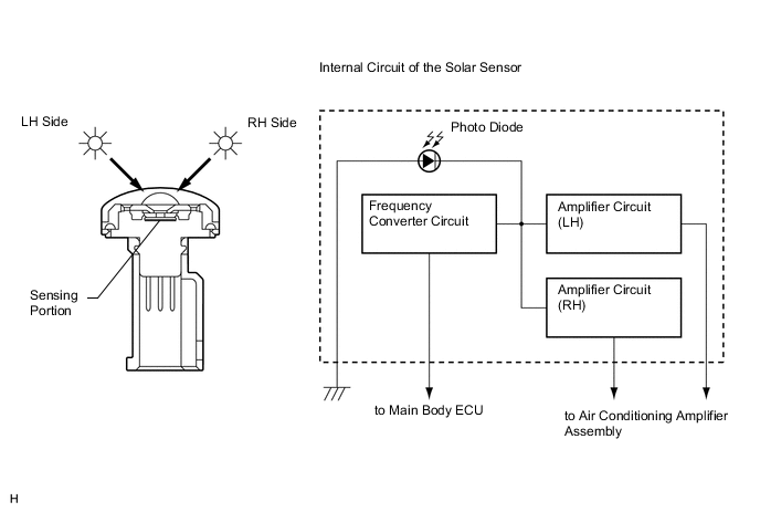
COOLER THERMISTOR (SOLAR SENSOR)
-
The cooler thermistor (solar sensor) consists of a photo diode, two amplifier circuits for the solar sensor and a frequency converter circuit for the light control sensor.
-
The cooler thermistor (solar sensor) detects (in the form of changes in the current that flows through the built-in photo diode) the changes in the amount of sunlight from the LH and RH sides (2 directions) and outputs these sunlight intensity signals to the air conditioning amplifier assembly.
-
-
AIR CONDITIONING PRESSURE SENSOR
The air conditioning pressure sensor detects the refrigerant pressure and outputs the pressure to the air conditioning amplifier assembly in the form of voltage changes.