AIR CONDITIONING SYSTEM(for Automatic Air Conditioning System) TERMINALS OF ECU
-
CHECK AIR CONDITIONING AMPLIFIER ASSEMBLY
-
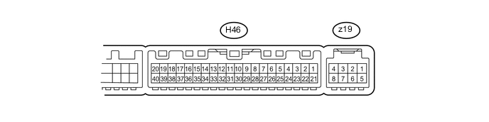
Disconnect the H46 air conditioning amplifier connector.
-
Measure the voltage and resistance according to the value(s) in the table below.
Terminal No. (Symbol) Wiring Color Terminal Description Condition Specified Condition H46-1 (IG+) - H46-14 (GND) Y - W-B Ignition power supply Ignition switch ON 11 to 14 V Ignition switch off Below 1 V H46-21 (B) - H46-14 (GND) W - W-B Battery power source Always 11 to 14 V H46-14 (GND) - Body ground W-B - Body ground Ground for main power supply Always Below 1 Ω
-
If the result is not as specified, there may be a malfunction on the wire harness side.
-
-
Reconnect the H46 air conditioning amplifier connector.
-
Measure the voltage and resistance according to the value(s) in the table below.
Terminal No. (Symbol) Wiring Color Terminal Description Condition Specified Condition z19-2 (BUS G) - Body ground - Ground for BUS IC Always Below 1 Ω H46-22 (BLW) - H46-14 (GND) R - W-B Blower motor control signal
-
Ignition switch ON
-
Blower switch LO
Pulse generation
(see waveform 1)
H46-10 (S5-3) - H46-13 (SG-2) B - G Power supply for air conditioning pressure sensor Ignition switch ON 4.75 to 5.25 V H46-9 (PRE) - H46-13 (SG-2) L - G Air conditioning pressure sensor signal
-
Ignition switch ON
-
Refrigerant pressure normal (less than 3.025 MPa [30.9 kgf/cm2, 438.6 psi] and more than 0.176 MPa [1.8 kgf/cm2, 25.5 psi])
0.70 to 4.69 V
-
Ignition switch ON
-
Refrigerant pressure abnormal (less than 0.176 MPa [1.8 kgf/cm2, 25.5 psi])
Below 0.70 V
-
Ignition switch ON
-
Refrigerant pressure abnormal (more than 3.025 MPa [30.9 kgf/cm2, 438.6 psi])
4.69 V or higher H46-30 (S5-1) - H46-14 (GND) LG - W-B Cooler thermistor (solar sensor) power source Ignition switch ON 4.5 to 5.5 V H46-33 (TSD) - H46-14 (GND) L - W-B Cooler thermistor (solar sensor) power signal (for driver side)
-
Ignition switch ON
-
Solar sensor subjected to electric light
-
Vehicle indoors
0.8 to 4.3 V
-
Ignition switch ON
-
Solar sensor covered with cloth
-
Vehicle indoors
Below 0.8 V H46-32 (TSP) - H46-14 (GND) P - W-B Cooler thermistor (solar sensor) power signal (for front passenger side)
-
Ignition switch ON
-
Solar sensor subjected to electric light
-
Vehicle indoors
0.8 to 4.3 V
-
Ignition switch ON
-
Solar sensor covered with cloth
-
Vehicle indoors
Below 0.8 V H46-29 (TR) - H46-34 (SG-1) GR - V Room temperature sensor signal
-
Ignition switch ON
-
Cabin temperature at 25°C (77°F)
1.8 to 2.2 V
-
Ignition switch ON
-
Cabin temperature at 40°C (104°F)
1.2 to 1.6 V H46-2 (SOL+) - H46-14 (GND) LG - W-B Compressor with pulley assembly operation signal
-
Engine running
-
A/C switch on
-
Blower switch LO
Pulse generation
(see waveform 2)
H46-40 (PTC1) - Body ground*1 W - Body ground HTR SUB NO.1 relay operation signal
-
Engine running (1250 rpm or more)
-
Temperature setting MAX HOT
-
Outside temperature 10°C (50°F) or less
-
Engine coolant temperature 75°C (167°F) or less
-
Headlight dimmer switch off
-
Blower switch off → on (after 30 seconds)
11 to 14 V → Below 1 V*2 H46-3 (PTC2) - Body ground*1 B - Body ground HTR SUB NO.2 relay operation signal
-
Engine running (1250 rpm or more)
-
Temperature setting MAX HOT
-
Outside temperature 10°C (50°F) or less
-
Engine coolant temperature 70°C (158°F) or less
-
Headlight dimmer switch off
-
Blower switch off → on (after 30 seconds)
11 to 14 V → Below 1 V*2 H46-39 (PTC3) - Body ground*1 BR - Body ground HTR SUB NO.3 relay operation signal
-
Engine running (1250 rpm or more)
-
Temperature setting MAX HOT
-
Outside temperature 10°C (50°F) or less
-
Engine coolant temperature 65°C (149°F) or less
-
Headlight dimmer switch off
-
Blower switch off → on (after 30 seconds)
11 to 14 V → Below 1 V*2 H46-27 (HLS)*1 - H46-14 (GND) BE - W-B Headlight signal (PTC heater control)
-
Engine started
-
Headlight dimmer switch off
11 to 14 V
-
Engine started
-
Headlight dimmer switch on
Below 1 V z19-5 (SGA) - Body ground - Ground for evaporator temperature sensor Always Below 1 Ω z19-6 (TEA) - z19-5 (SGA) - Evaporator temperature sensor signal
-
Ignition switch ON
-
Evaporator temperature at 0°C (32°F)
1.7 to 2.1 V
-
Ignition switch ON
-
Evaporator temperature at 15°C (59°F)
0.9 to 1.3 V z19-3 (BUS) - z19-2 (BUS G) - BUS IC control signal Ignition switch ON Pulse generation z19-4 (B BUS) - z19-2 (BUS G) - Power supply for BUS IC Always 11 to 14 V
-
*1: w/ PTC Heater
Tech Tips
*2: After the measurement conditions are met, wait 30 seconds before performing measurements.
-
If the result is not as specified, the air conditioning amplifier assembly may have a malfunction.
-
-
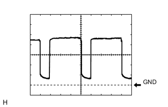
Using an oscilloscope, check waveform 1.
Blower Motor Control Signal Item Content Terminal No. (Symbol) H46-22 (BLW) - H46-14 (GND) Tool Setting 1 V/DIV., 500 μs/DIV. Condition
-
Ignition switch ON
-
Blower switch LO
Tech Tips
When the blower level is increased, the duty ratio changes accordingly.
-
-
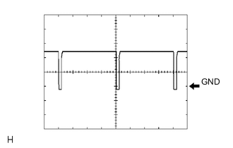
Using an oscilloscope, check waveform 2.
Compressor with Pulley Operation Signal Item Content Terminal No. (Symbol) H46-2 (SOL+) - H46-14 (GND) Tool Setting 5 V/DIV., 500 μs/DIV. Condition
-
Engine running
-
A/C switch on
-
Blower switch LO
-
-
-
CHECK AIR CONDITIONING CONTROL ASSEMBLY

-
Disconnect the H21 control connector.
-
Measure the resistance and voltage according to the value(s) in the table below.
Terminal No. (Symbol) Wiring Color Terminal Description Condition Specified Condition H21-2 (IG+) - H21-5 (GND) R - BR Ignition power supply Ignition switch ON 11 to 14 V Ignition switch off Below 1 V H21-5 (GND) - Body ground BR - Body ground Ground Always Below 1 Ω If the result is not as specified, there may be a malfunction on the wire harness side.
-
-
CHECK MAIN BODY ECU (INSTRUMENT PANEL JUNCTION BLOCK ASSEMBLY)
-
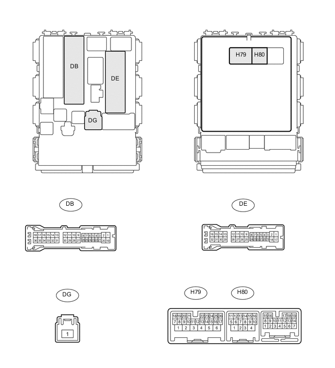
Disconnect the DB, DE, DG and H80 ECU connectors.
-
Measure the voltage and resistance according to the value(s) in the table below.
Terminal No. (Symbol) Wiring Color Terminal Description Condition Specified Condition DE-28 (GND1) - Body ground W-B - Body ground Ground Always Below 1 Ω H80-4 (GND2) - Body ground W-B - Body ground Ground Always Below 1 Ω DB-30 (BECU) - Body ground W - Body ground Power source Always 11 to 14 V DG-1 (ALTB) - Body ground W - Body ground Power source Always 11 to 14 V If the result is not as specified, there may be a malfunction on the wire harness side.
-
Reconnect the DB, DE, DG and H80 ECU connectors.
-
Measure the voltage according to the value(s) in the table below.
Terminal No. (Symbol) Wiring Color Terminal Description Condition Specified Condition H79-20 (HRLY) - DE-28 (GND1)* B - W-B H-LP relay drive output Headlight dimmer switch in head position Below 1 V Headlight dimmer switch not in head position 11 to 14 V
-
*: w/ PTC Heater
-
If the result is not as specified, the main body ECU (instrument panel junction block assembly) may have a malfunction.
-
-