PRE-COLLISION SYSTEM, Diagnostic DTC:C1A4B
| DTC Code | DTC Name |
|---|---|
| C1A4B | Stop Light Relay Circuit |
DESCRIPTION
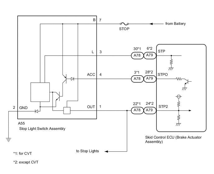
The skid control ECU (brake actuator assembly) sends a stop light operation request signal to the stop light relay (stop light switch assembly). If the skid control ECU (brake actuator assembly) detects a malfunction in the stop light relay circuit, the driving support ECU assembly stores DTC C1A4B.
| DTC No. | DTC Detection Condition | Trouble Area |
|---|---|---|
| C1A4B |
|
|
WIRING DIAGRAM
CAUTION / NOTICE / HINT
Note
-
When this DTC is output, a malfunction in the lighting system is suspected. Check if the lighting system is functioning normally Click here.
-
Inspect the fuses for circuits related to this system before performing the following procedure.
-
When replacing the pre-collision city sensor, replace it with a new one and be sure to initialize the settings. If a pre-collision city sensor which was installed to another vehicle is used, the information stored in the pre-collision city sensor will not match the information from the vehicle and, as a result, a DTC may be stored.
-
If the pre-collision city sensor has been replaced, or the windshield glass has been replaced or removed/installed, be sure to perform Pre-collision City Sensor Learning Click here.
-
w/ Smart Entry and Start System:
When the start function does not operate, check the entry and start system (for start function) Click here.
PROCEDURE
-
CHECK STOP LIGHT OPERATION
-
Check that the stop lights come on when the brake pedal is depressed and go off when the brake pedal is released.
OK The stop lights illuminate when the brake pedal is depressed. The stop lights turn off when the brake pedal is released.
NG 
GO TO LIGHTING SYSTEM Click here
OK 
-
-
INSPECT STOP LIGHT SWITCH ASSEMBLY
-
Inspect the stop light switch assembly Click here.
OK The stop light switch assembly is normal.
NG
REPLACE STOP LIGHT SWITCH ASSEMBLY Click here
OK
-
-
CHECK FOR DTCs (VEHICLE STABILITY CONTROL SYSTEM)
-
Connect the GTS to the DLC3.
-
Turn the ignition switch to ON.
-
Turn the GTS on.
-
Enter the following menus: Chassis / ABS/VSC/TRAC / Trouble Codes.
-
Check for DTCs Click here.
Result Result Proceed to Vehicle stability control system DTCs are not output A Vehicle stability control system DTCs are output B
B
GO TO VEHICLE STABILITY CONTROL SYSTEM (DIAGNOSTIC TROUBLE CODE CHART) Click here
A
-
-
CHECK HARNESS AND CONNECTOR (STPO TERMINAL VOLTAGE)
-
Turn the ignition switch off.
-
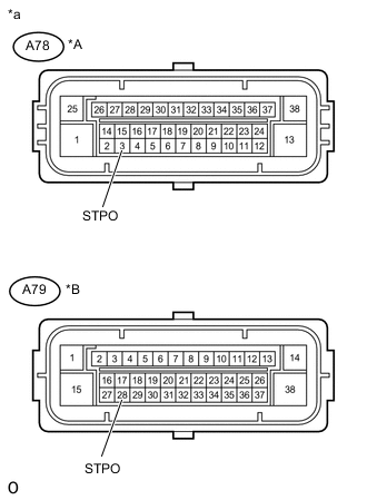
Text in Illustration *A for CVT *B except CVT *a Front view of wire harness connector
(to Skid Control ECU (Brake Actuator Assembly))
Disconnect the A78*1 or A79*2 skid control ECU (brake actuator assembly) connector.
-
*1: for CVT
-
*2: except CVT
-
-
Measure the voltage according to the value(s) in the table below.
Standard Voltage for CVT: Tester Connection Condition Specified Condition A78-3 (STPO) - Body ground Ignition switch ON 11 to 14 V except CVT: Tester Connection Condition Specified Condition A79-28 (STPO) - Body ground Ignition switch ON 11 to 14 V -
Connect the A78*1 or A79*2 skid control ECU (brake actuator assembly) connector.
-
*1: for CVT
-
*2: except CVT
-
NG 
CHECK HARNESS AND CONNECTOR (STOP LIGHT SWITCH ASSEMBLY - SKID CONTROL ECU) Click here
OK
-
-
PERFORM ACTIVE TEST USING GTS (STOP LIGHT RELAY OUTPUT)
-
According to the display on the GTS, perform the Active Test Stop Light Relay Click here.
Chassis > ABS/VSC/TRAC > Active Test Tester Display Test Part Control Range Diagnostic Note Stop Light Relay Stop light control relay Relay ON / OFF Stop lights come on. -
According to the display on the GTS, read the Data List item Stop Light Relay Output Click here.
Chassis > ABS/VSC/TRAC > Data List Tester Display Measurement Item/Range Normal Condition Diagnostic Note Stop Light Relay Output Stop light control relay output/ ON or OFF ON: Relay output on
OFF: Relay output off
- -
Check that the Data List item Stop Light Relay Output changes between ON and OFF and the stop lights turn on and off according to the operation of the Active Test.
Result Result Proceed to The Data List item Stop Light Relay Output does not change between ON and OFF and the stop lights do not turn ON and OFF according to the operation of the Active Test. A The Data List item Stop Light Relay Output changes between ON and OFF but the stop lights do not turn ON and OFF according to the operation of the Active Test. B
NG
CHECK HARNESS AND CONNECTOR (STOP LIGHT SWITCH ASSEMBLY - SKID CONTROL ECU) Click here
OK
-
-
INSPECT SKID CONTROL ECU (BRAKE ACTUATOR ASSEMBLY)
-
According to the display on the GTS, perform the Active Test Stop Light Relay Click here.
Chassis > ABS/VSC/TRAC > Active Test Tester Display Test Part Control Range Diagnostic Note Stop Light Relay Stop light control relay Relay ON / OFF Stop lights come on. -
Measure the voltage according to the value(s) in the table below.
Tech Tips
Do not disconnect the stop light switch assembly connector.
Standard Voltage Tester Connection Condition Specified Condition A55-4 (ACC) - Body ground Ignition switch ON
(Active test OFF)
11 to 14 V Ignition switch ON
(Active test ON)
Below 1.5 V
OK
REPLACE STOP LIGHT SWITCH ASSEMBLY Click here
NG
REPLACE SKID CONTROL ECU (BRAKE ACTUATOR ASSEMBLY) Click here
-
-
CHECK HARNESS AND CONNECTOR (STOP LIGHT SWITCH ASSEMBLY - SKID CONTROL ECU)
-
Turn the ignition switch off.
-
Disconnect the A55 stop light switch assembly connector.
-
Disconnect the A78*1 or A79*2 skid control ECU (brake actuator assembly) connector.
-
*1: for CVT
-
*2: except CVT
-
-
Measure the resistance according to the value(s) in the table below.
Standard Resistance for CVT: Tester Connection Condition Specified Condition A55-1 (OUT) - A78-22 (STP2) Always Below 1 Ω except CVT: Tester Connection Condition Specified Condition A55-1 (OUT) - A79-24 (STP2) Always Below 1 Ω -
Connect the A78*1 or A79*2 skid control ECU (brake actuator assembly) connector.
-
*1: for CVT
-
*2: except CVT
-
-
Connect the A55 stop light switch assembly connector.
OK
REPLACE SKID CONTROL ECU (BRAKE ACTUATOR ASSEMBLY) Click here
NG
REPAIR OR REPLACE HARNESS OR CONNECTOR (STOP LIGHT SWITCH ASSEMBLY - SKID CONTROL ECU)
-
-
CHECK HARNESS AND CONNECTOR (STOP LIGHT SWITCH ASSEMBLY - SKID CONTROL ECU)
-
Turn the ignition switch off.
-
Disconnect the A55 stop light switch assembly connector.
-
Disconnect the A78*1 or A79*2 skid control ECU (brake actuator assembly) connector.
-
*1: for CVT
-
*2: except CVT
-
-
Measure the resistance according to the value(s) in the table below.
Standard Resistance for CVT: Tester Connection Condition Specified Condition A55-4 (ACC) - A78-3 (STPO) Always Below 1 Ω A55-4 (ACC) or A78-3 (STPO) - Body ground Always 10 kΩ or higher except CVT: Tester Connection Condition Specified Condition A55-4 (ACC) - A79-28 (STPO) Always Below 1 Ω A55-4 (ACC) or A79-28 (STPO) - Body ground Always 10 kΩ or higher -
Connect the A78*1 or A79*2 skid control ECU (brake actuator assembly) connector.
-
*1: for CVT
-
*2: except CVT
-
-
Connect the A55 stop light switch assembly connector.
OK
REPLACE STOP LIGHT SWITCH ASSEMBLY Click here
NG
REPAIR OR REPLACE HARNESS OR CONNECTOR (STOP LIGHT SWITCH ASSEMBLY - SKID CONTROL ECU)
-