LIGHTING SYSTEM Footwell Light Circuit
DESCRIPTION
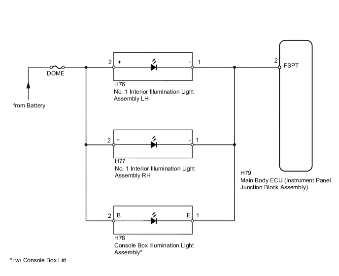
The main body ECU receives information regarding the door lock position switch and ignition switch, and turns on each No. 1 interior illumination light and the console box illumination light*.
-
*: w/ Console Box Lid
WIRING DIAGRAM
CAUTION / NOTICE / HINT
Tech Tips
Inspect the fuses for circuits related to this system before performing the following inspection procedure.
PROCEDURE
-
PERFORM ACTIVE TEST USING INTELLIGENT TESTER (MAIN BODY ECU)
-
*: w/ Console Box Lid
-
Connect the intelligent tester to the DLC3.
-
Turn the ignition switch to ON.
-
Turn the intelligent tester on.
-
Turn the map light switch to the DOOR position.
-
Enter the following menus: Body / Main Body / Active Test / Step light Operation.
-
Use the Active Test to check the operation of the No. 1 interior illumination lights and console box illumination light*.
Main Body Tester Display Test Part Control Range Diagnostic Note Step light Operation No. 1 interior illumination lights and console box illumination light* ON/OFF - OK No. 1 interior illumination lights and console box illumination light* come on. Result Result Proceed to OK A NG (No. 1 interior illumination lights do not come on) B NG (Console box illumination light does not come on)* C
A 
PROCEED TO NEXT SUSPECTED AREA SHOWN IN PROBLEM SYMPTOMS TABLE Click here
C 
INSPECT CONSOLE BOX ILLUMINATION LIGHT ASSEMBLY Click here
B 
-
-
INSPECT NO. 1 INTERIOR ILLUMINATION LIGHT ASSEMBLY
-
Remove the No. 1 interior illumination light LH Click here.
-
Remove the No. 1 interior illumination light RH Click here.
-
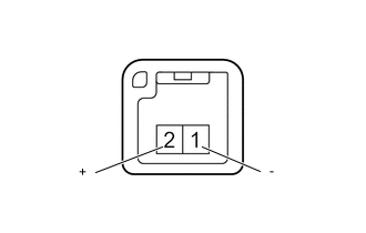
Connect the positive (+) lead from the battery to terminal 2 and the negative (-) lead to terminal 1, and check that the light comes on.
OK Light comes on. Result Result Proceed to OK A NG (for LH) B NG (for RH) C
B
REPLACE NO. 1 INTERIOR ILLUMINATION LIGHT ASSEMBLY Click here
C
REPLACE NO. 1 INTERIOR ILLUMINATION LIGHT ASSEMBLY Click here
A
-
-
CHECK HARNESS OR CONNECTOR (NO. 1 INTERIOR ILLUMINATION LIGHT ASSEMBLY - MAIN BODY ECU AND BATTERY)
-
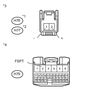
Text in Illustration *1 for LH *2 for RH *3 Front view of wire harness connector
(to No. 1 Interior Illumination Light Assembly)
*4 Front view of wire harness connector
(to Main Body ECU)
Disconnect the H79 main body ECU connector.
-
Disconnect the H76*1 or H77*2 No. 1 interior illumination light connector.
-
*1: for LH
-
*2: for RH
-
-
Measure the voltage and resistance according to the value(s) in the table below.
Standard Voltage for LH Tester Connection Condition Specified Condition H76-2 (+) - Body ground Always 11 to 14 V for RH Tester Connection Condition Specified Condition H77-2 (+) - Body ground Always 11 to 14 V Standard Resistance for LH Tester Connection Condition Specified Condition H76-1 (-) - H79-2 (FSPT) Always Below 1 Ω H76-1 (-) - Body ground Always 10 kΩ or higher for RH Tester Connection Condition Specified Condition H77-1 (-) - H79-2 (FSPT) Always Below 1 Ω H77-1 (-) - Body ground Always 10 kΩ or higher
OK
REPLACE MAIN BODY ECU (INSTRUMENT PANEL JUNCTION BLOCK ASSEMBLY)
NG
REPAIR OR REPLACE HARNESS OR CONNECTOR
-
-
INSPECT CONSOLE BOX ILLUMINATION LIGHT ASSEMBLY
-
Remove the console box illumination light Click here.
-
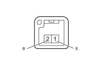
Connect the positive (+) lead from the battery to terminal 2 and the negative (-) lead to terminal 1, and check that the light comes on.
OK Light comes on.
NG
REPLACE CONSOLE BOX ILLUMINATION LIGHT ASSEMBLY Click here
OK
-
-
CHECK HARNESS OR CONNECTOR (CONSOLE BOX ILLUMINATION LIGHT ASSEMBLY - MAIN BODY ECU AND BATTERY)
-
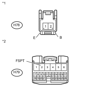
Text in Illustration *1 Front view of wire harness connector
(to Console Box Illumination Light Assembly)
*2 Front view of wire harness connector
(to Main Body ECU)
Disconnect the H79 main body ECU connector.
-
Disconnect the H78 console box interior illumination light connector.
-
Measure the voltage and resistance according to the value(s) in the table below.
Standard Voltage Tester Connection Condition Specified Condition H78-2 (B) - Body ground Always 11 to 14 V Standard Resistance Tester Connection Condition Specified Condition H78-1 (E) - H79-2 (FSPT) Always Below 1 Ω H78-1 (E) - Body ground Always 10 kΩ or higher
OK
REPLACE MAIN BODY ECU (INSTRUMENT PANEL JUNCTION BLOCK ASSEMBLY)
NG
REPAIR OR REPLACE HARNESS OR CONNECTOR
-