ENGINE IMMOBILISER SYSTEM(w/ Entry and Start System) Security Indicator Light Circuit
DESCRIPTION
-
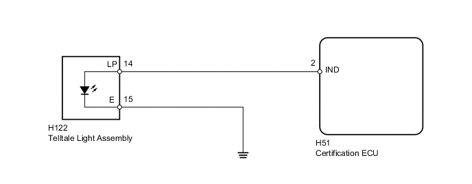
When the engine immobiliser system is set, the security indicator flashes continuously, but does not illuminate if the engine immobiliser system is not set.
WIRING DIAGRAM
PROCEDURE
-
PERFORM ACTIVE TEST USING INTELLIGENT TESTER (SECURITY INDICATOR)
-
Check that the security indicator light illuminates when operating it with the Active Test Click here.
Entry&Start Tester Display Test Part Control Range Diagnostic Note Security Indicator Security indicator ON/OFF - OK Security indicator illuminates.
OK 
REPLACE CERTIFICATION ECU
NG 
-
-
INSPECT TELLTALE LIGHT ASSEMBLY
-
*1 Battery (-) *2 Battery (+) Remove the telltale light assembly Click here.
-
Connect the positive (+) lead from the battery to terminal 14 and the negative (-) lead to terminal 15, and check that the security indicator illuminates.
OK Security indicator illuminates.
NG
REPLACE TELLTALE LIGHT ASSEMBLY Click here
OK
-
-
CHECK HARNESS AND CONNECTOR (TELLTALE LIGHT ASSEMBLY - CERTIFICATION ECU AND BODY GROUND)
-
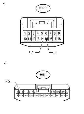
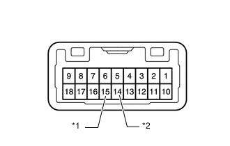
Text in Illustration *1 Front view of wire harness connector
(to Telltale Light Assembly)
*2 Front view of wire harness connector
(to Certification ECU)
Disconnect the H122 light connector.
-
Disconnect the H51 ECU connector.
-
Measure the resistance according to the value(s) in the table below.
Standard Resistance Tester Connection Condition Specified Condition H122-14 (LP) - H51-2 (IND) Always Below 1 Ω H122-15 (E) - Body ground Always Below 1 Ω H122-14 (LP) or H51-2 (IND) - Body ground Always 10 kΩ or higher
OK
REPLACE CERTIFICATION ECU
NG
REPAIR OR REPLACE HARNESS OR CONNECTOR
-