ENGINE IMMOBILISER SYSTEM(w/ Entry and Start System), Diagnostic DTC:B279A
| DTC Code | DTC Name |
|---|---|
| B279A | Theft Deterrent System Communication Line High Fixation |
DESCRIPTION
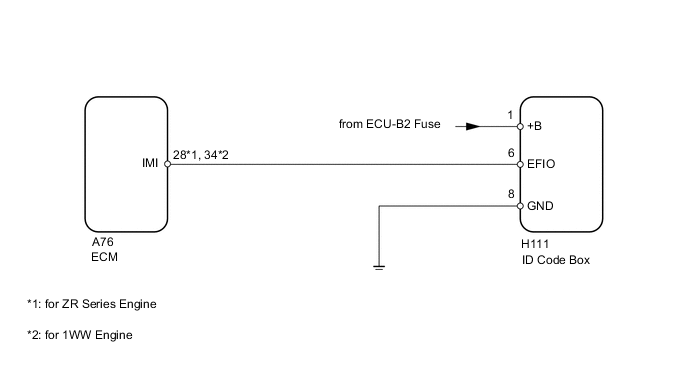
If the communication line (EFIO-IMI) to the ID code box is stuck on HI output, the ECM stores this DTC.
| DTC Code | DTC Detection Condition | Trouble Area |
|---|---|---|
| B279A | The communication line (EFIO-IMI) between the ECM and the ID code box is stuck on HI output. |
|
WIRING DIAGRAM
CAUTION / NOTICE / HINT
Note
-
When the ID code box is replaced, reregister the recognition codes and ECU communication ID.
-
for 1WW:
After turning the engine switch off, make sure to wait at least 6 minutes before disconnecting the ECM connector or replacing the ECM.
PROCEDURE
-
CLEAR DTC
-
Clear the DTCs Click here.
NEXT 
-
-
CHECK FOR DTC
-
Check for DTCs Click here.
Tech Tips
If DTCs other than DTC B279A are output, troubleshoot those DTCs first.
Result Result Proceed to DTC B279A is output A DTC B279A and other DTCs are output B
B 
Go to DIAGNOSTIC TROUBLE CODE CHART Click here
A
-
-
CHECK HARNESS AND CONNECTOR (ID CODE BOX - ECM)
-
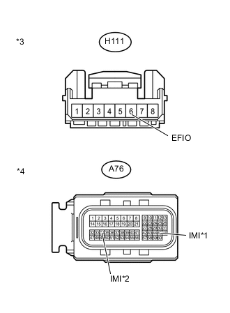
Text in Illustration *1 for ZR Series Engine *2 for 1WW Engine *3 Front view of wire harness connector
(to ID Code Box)
*4 Front view of wire harness connector
(to ECM)
Disconnect the H111 box connector.
-
Disconnect the A76 ECM connector.
-
Measure the resistance according to the value(s) in the table below.
Standard Resistance for ZR Series Engine Tester Connection Condition Specified Condition H111-6 (EFIO) - A76-28 (IMI) Always Below 1 Ω H111-6 (EFIO) or A76-28 (IMI) - Body ground Always 10 kΩ or higher for 1WW Engine Tester Connection Condition Specified Condition H111-6 (EFIO) - A76-34 (IMI) Always Below 1 Ω H111-6 (EFIO) or A76-34 (IMI) - Body ground Always 10 kΩ or higher
NG
REPAIR OR REPLACE HARNESS OR CONNECTOR
OK
-
-
CHECK ID CODE BOX (OUTPUT)
-
Using an oscilloscope, check the waveform.
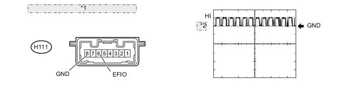
*1 Component with harness connected: (ID Code Box) *2 LOW Measurement Condition Item Content Tester Connection H111-6 (EFIO) - H111-8 (GND) Tool Setting 10 V/DIV., 100 msec./DIV. Condition Engine switch on (IG) OK Waveform is output normally (refer to illustration). Tech Tips
If replacing the ECM, refer to the procedures below.
-
for 1ZR-FAE: Click here
-
for 2ZR-FAE: Click here
-
for 1WW: Click here
-
OK
REPLACE ECM
NG
-
-
CHECK ID CODE BOX (POWER SOURCE AND BODY GROUND)
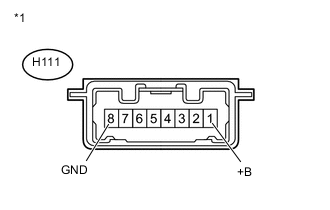
Text in Illustration *1 Component with harness connected
(ID Code Box)
-
Measure the voltage according to the value(s) in the table below.
Standard Voltage Tester Connector Condition Specified Condition H111-1 (+B) - H111-8 (GND) Always 11 to 14 V
NG
REPAIR OR REPLACE HARNESS OR CONNECTOR
OK
-
-
REPLACE ID CODE BOX
-
Replace the ID code box.
NEXT
-
-
REGISTER RECOGNITION CODES
-
Register the recognition codes in the ECUs.
NEXT
-
-
REGISTER ECU COMMUNICATION ID
-
Register the ECU communication ID.
NEXT
-
-
CLEAR DTC
-
Clear the DTCs Click here.
NEXT
-
-
CHECK FOR DTC
-
Check for DTCs Click here.
OK DTC B279A is not output. Tech Tips
If replacing the ECM, refer to the procedures below.
-
for 1ZR-FAE: Click here
-
for 2ZR-FAE: Click here
-
for 1WW: Click here
-
OK
END (ID CODE BOX IS DEFECTIVE)
NG
REPLACE ECM
-