CAN COMMUNICATION SYSTEM SYSTEM DIAGRAM
-
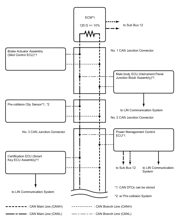
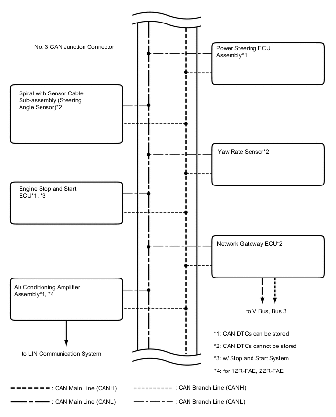
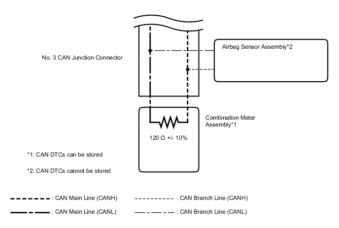
SYSTEM DIAGRAM (w/ Entry and Start System)
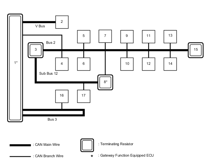
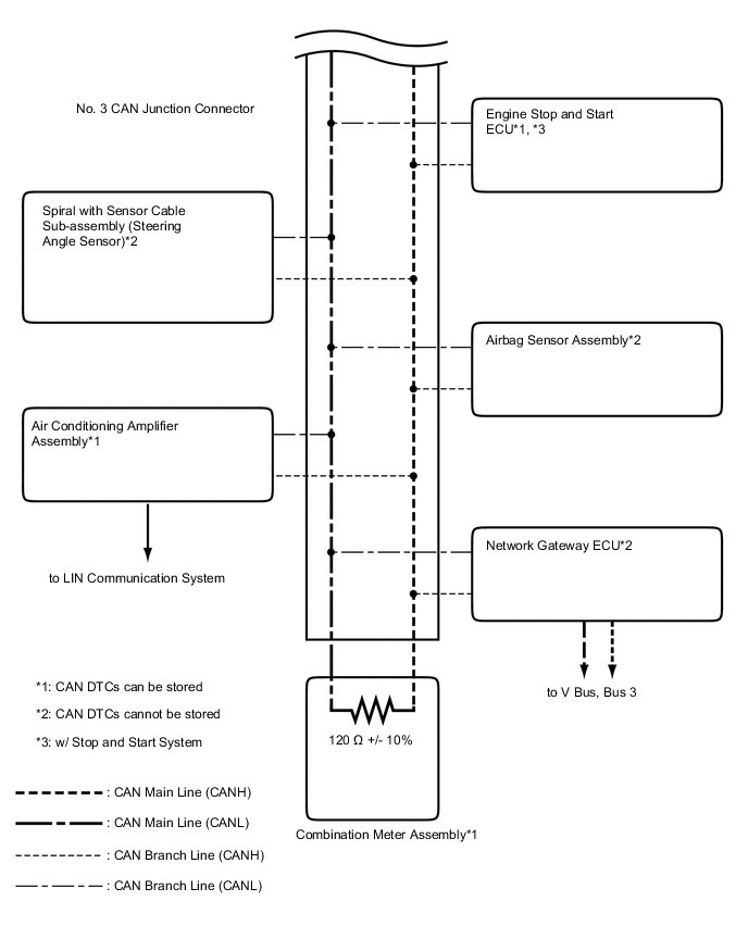
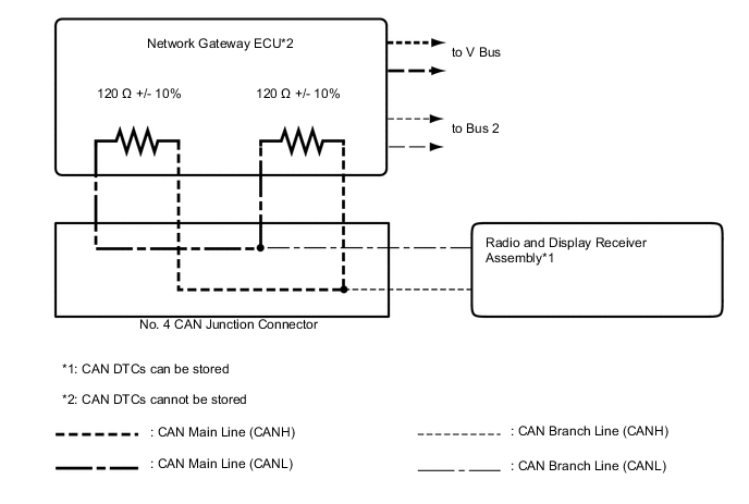
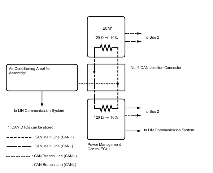
No. ECU/Sensor Name 1 Network gateway ECU 2 DLC3 3 ECM 4 Brake actuator assembly (skid control ECU) 5 Pre-collision city sensor*1 6 Certification ECU (smart key ECU assembly) 7 Power steering ECU assembly 8 Power management control ECU 9 Yaw rate sensor 10 Spiral with sensor cable sub-assembly (steering angle sensor) 11 Airbag sensor assembly 12 Engine stop and start ECU*2 13 Air conditioning amplifier assembly*3 14 Main body ECU (instrument panel junction block assembly) 15 Combination meter assembly 16 Radio and display receiver assembly*4 17 Air conditioning amplifier assembly*5
-
*1: w/ Pre-collision System
-
*2: w/ Stop and Start System
-
*3: for 1ZR-FAE, 2ZR-FAE
-
*4: for Radio and Display Type
-
*5: for 1WW
-
-
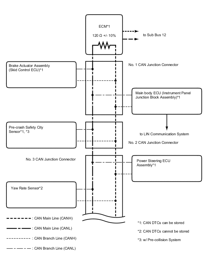
SYSTEM DIAGRAM (w/o Entry and Start System)
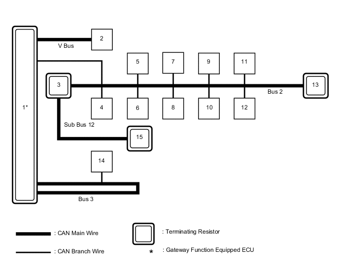
No. ECU/Sensor Name 1 Network gateway ECU 2 DLC3 3 ECM 4 Brake actuator assembly (skid control ECU) 5 Pre-collision city sensor*1 6 Power steering ECU assembly 7 Yaw rate sensor 8 Spiral with sensor cable sub-assembly (steering angle sensor) 9 Airbag sensor assembly 10 Engine stop and start ECU*2 11 Air conditioning amplifier assembly 12 Main body ECU (instrument panel junction block assembly) 13 Combination meter assembly 14 Radio and display receiver assembly*3 15 Power management control ECU
-
*1: w/ Pre-collision System
-
*2: w/ Stop and Start System
-
*3: for Radio and Display Type
-
-
V Bus
-
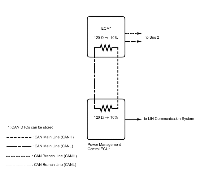
Bus 2 (w/ Entry and Start System)
-
Bus 2 (w/o Entry and Start System)
-
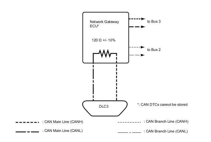
Bus 3 (for Radio and Display Type)
-
Sub Bus 12 (for 1WW [w/ Entry and Start System])
-
Sub Bus 12 (for 1WW [w/o Entry and Start System])