POWER DOOR LOCK CONTROL SYSTEM Collision Door Lock Release Function does not Operate
DESCRIPTION
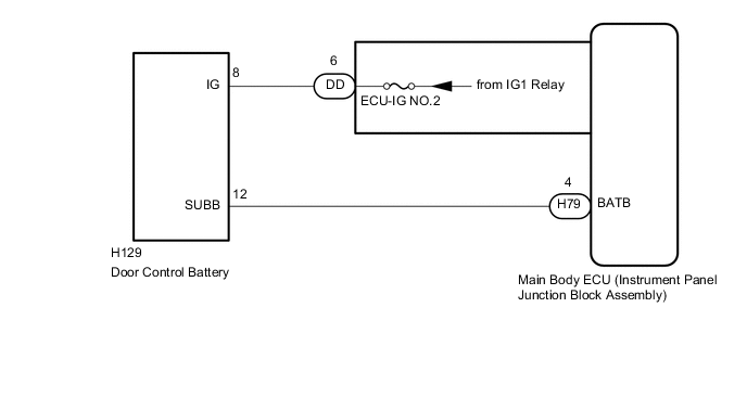
When an impact is detected, a relay inside the main body ECU (instrument panel junction block assembly) is operated to switch the power source of the door lock with motor assemblies from the vehicle battery to the door control battery.
WIRING DIAGRAM
CAUTION / NOTICE / HINT
Note
Inspect the fuses for circuits related to this system before performing the following procedure.
PROCEDURE
-
CHECK DOOR LOCK OPERATION
-
Check door lock operation Click here.
OK All doors lock and unlock normally.
NG 
GO TO PROBLEM SYMPTOMS TABLE Click here
OK 
-
-
CHECK DOOR CONTROL BATTERY
-
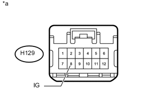
Text in Illustration *a Front view of wire harness connector
(to Door Control Battery)
Disconnect the door control battery connector.
-
Measure the voltage according to the value(s) in the table below.
Standard Voltage Tester Connection Switch Condition Specified Condition H129-8 (IG) - Body ground Ignition switch ON 11 to 14 V
NG 
CHECK HARNESS AND CONNECTOR (MAIN BODY ECU [INSTRUMENT PANEL JUNCTION BLOCK ASSEMBLY] - DOOR CONTROL BATTERY) Click here
OK
-
-
CHECK HARNESS AND CONNECTOR (MAIN BODY ECU [INSTRUMENT PANEL JUNCTION BLOCK ASSEMBLY] - DOOR CONTROL BATTERY)
-
Disconnect the H79 main body ECU (instrument panel junction block assembly) connector.
-
Disconnect the H129 door control battery connector.
-
Measure the resistance according to the value(s) in the table.
Standard Resistance Tester Connection Condition Specified Condition H79-4 (BATB) - H129-12 (SUBB) Always Below 1 Ω H79-4 (BATB) or H129-12 (SUBB) - Body ground Always 10 kΩ or higher
NG
REPAIR OR REPLACE HARNESS OR CONNECTOR
OK
-
-
REPLACE DOOR CONTROL BATTERY
-
Replace the door control battery with new or known good one Click here.
NEXT
-
-
CHECK DOOR CONTROL BATTERY
-
Check door control battery operation Click here.
OK Collision detection door lock function operates normally.
OK
END (DOOR CONTROL BATTERY WAS DEFECTIVE)
NG
REPLACE MAIN BODY ECU (INSTRUMENT PANEL JUNCTION BLOCK ASSEMBLY)
-
-
CHECK HARNESS AND CONNECTOR (MAIN BODY ECU [INSTRUMENT PANEL JUNCTION BLOCK ASSEMBLY] - DOOR CONTROL BATTERY)
-
Disconnect the DD main body ECU (instrument panel junction block assembly) connector.
-
Disconnect the H129 door control battery connector.
-
Measure the resistance according to the value(s) in the table.
Standard Resistance Tester Connection Condition Specified Condition DD-6 - H129-8 (IG) Always Below 1 Ω DD-6 or H129-8 (IG) - Body ground Always 10 kΩ or higher
OK
REPLACE MAIN BODY ECU (INSTRUMENT PANEL JUNCTION BLOCK ASSEMBLY)
NG
REPAIR OR REPLACE HARNESS OR CONNECTOR
-