POWER DOOR LOCK CONTROL SYSTEM All Doors LOCK/UNLOCK Functions do not Operate Via Master Switch, Driver Side Door Key Cylinder
DESCRIPTION
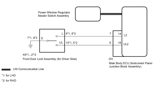
The main body ECU (instrument panel junction block assembly) receives switch signals from the power window regulator master switch assembly, and driver side door key cylinder switch signals from the front door lock. The main body ECU (instrument panel junction block assembly) activates the door lock motor on each door according to these signals.
WIRING DIAGRAM
CAUTION / NOTICE / HINT
Note
As the door control battery is installed between the vehicle battery and main body ECU (instrument panel junction block assembly), first perform the inspections in On-Vehicle Inspection to confirm that there are no malfunctions in the power source circuit for the main body ECU (instrument panel junction block assembly) before performing this troubleshooting procedure Click here.
PROCEDURE
-
CHECK DOOR LOCK OPERATION
-
Check the door lock operation.
Result Result Proceed to All doors cannot be locked by power window regulator master switch assembly A All doors cannot be locked with driver side door key cylinder B
B 
READ VALUE USING INTELLIGENT TESTER (DOOR KEY-LINKED LOCK AND UNLOCK SWITCH) Click here
A 
-
-
READ VALUE USING INTELLIGENT TESTER (D-Door Lock Pos SW, P-Door Lock Pos SW)
-
Use the Data List to check if the door key-linked lock and unlock switches are functioning properly.
Main Body ECU Tester Display Measurement Item/Range Normal Condition Diagnostic Note D-Door Lock Pos SW Driver side door lock position switch signal / ON or OFF ON: Driver side door unlocked
OFF: Driver side door locked
- P-Door Lock Pos SW Front passenger side door lock position switch signal / ON or OFF ON: Front passenger side door unlocked
OFF: Front passenger side door locked
- OK On the intelligent tester screen, ON and OFF is displayed for each item according to the table below.
OK 
REPLACE MAIN BODY ECU (INSTRUMENT PANEL JUNCTION BLOCK ASSEMBLY)
NG
-
-
REPLACE POWER WINDOW REGULATOR MASTER SWITCH ASSEMBLY
-
Replace the power window regulator master switch assembly with a new or known good one Click here.
NEXT
-
-
CHECK DOOR LOCK OPERATION
-
Check that all doors can be locked and unlocked by the power window regulator master switch assembly Click here.
OK
END (POWER WINDOW REGULATOR MASTER SWITCH ASSEMBLY WAS DEFECTIVE)
NG
REPLACE MAIN BODY ECU (INSTRUMENT PANEL JUNCTION BLOCK ASSEMBLY)
-
-
READ VALUE USING INTELLIGENT TESTER (DOOR KEY-LINKED LOCK AND UNLOCK SWITCH)
-
Use the Data List to check if the door key-linked lock and unlock switches are functioning properly.
Main Body ECU Tester Display Measurement Item/Range Normal Condition Diagnostic Note Door Key Linked Lock SW Door key-linked switch lock signal / ON or OFF ON: Driver side door key cylinder turned to lock position
OFF: Driver side door key cylinder not turned
- Door Key Linked Unlock SW Door key-linked switch unlock signal / ON or OFF ON: Driver side door key cylinder turned to unlock position
OFF: Driver side door key cylinder not turned
- OK On the intelligent tester screen, ON and OFF is displayed for each item according to the table below.
OK
REPLACE MAIN BODY ECU (INSTRUMENT PANEL JUNCTION BLOCK ASSEMBLY)
NG
-
-
INSPECT FRONT DOOR LOCK ASSEMBLY (for Driver Side)
-
Remove the front door lock assembly (for Driver Side) Click here.
-
Inspect the front door lock assembly (for Driver Side) Click here.
NG
REPLACE FRONT DOOR LOCK ASSEMBLY (for Driver Side) Click here
OK
-
-
CHECK HARNESS AND CONNECTOR (FRONT DOOR LOCK ASSEMBLY [for Driver Side] - MAIN BODY ECU AND BODY GROUND)
-
Disconnect the K9*1 or J7*2 front door lock assembly (for Driver Side) connector.
-
Disconnect the DH main body ECU (instrument panel junction block assembly) connector
-
Measure the resistance according to the value(s) in the table below.
Standard Resistance for LHD Tester Connection Condition Specified Condition K9-10 (UL) - DH-6 (UL2) Always Below 1 Ω K9-9 (L) - DH-7 (L2) Always Below 1 Ω K9-7 (E) - Body ground Always Below 1 Ω K9-10 (UL) or DH-6 (UL2) - Body ground Always 10 kΩ or higher K9-9 (L) or DH-7 (L2) - Body ground Always 10 kΩ or higher for RHD Tester Connection Condition Specified Condition J7-5 (UL) - DH-6 (UL2) Always Below 1 Ω J7-6 (L) - DH-7 (L2) Always Below 1 Ω J7-8 (E) - Body ground Always Below 1 Ω J7-5 (UL) or DH-6 (UL2) - Body ground Always 10 kΩ or higher J7-6 (L) or DH-7 (L2) - Body ground Always 10 kΩ or higher
OK
REPLACE MAIN BODY ECU (INSTRUMENT PANEL JUNCTION BLOCK ASSEMBLY)
NG
REPAIR OR REPLACE HARNESS OR CONNECTOR
-