LIN COMMUNICATION SYSTEM TERMINALS OF ECU
-
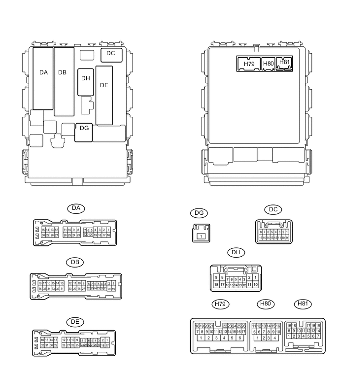
CHECK MAIN BODY ECU (INSTRUMENT PANEL JUNCTION BLOCK ASSEMBLY)
-
Disconnect the H80, DB and DE ECU connectors.
-
Measure the resistance and voltage according to the value(s) in the table below.
Terminal No. (Symbol) Wiring Color Terminal Description Condition Specified Condition H80-4 (GND2) - Body ground W-B - Body ground Ground Always Below 1 Ω DE-28 (GND1) - Body ground W-B - Body ground Ground Always Below 1 Ω DH-12 (BECU) - Body ground B - Body ground Battery power supply Always 11 to 14 V If the result is not as specified, there may be a malfunction on the wire harness side.
-
-
CHECK POWER WINDOW REGULATOR MASTER SWITCH ASSEMBLY

Text in Illustration *1 for LHD *2 for RHD
-
Disconnect the K5*1 or J5*2 master switch connector.
-
*1: for LHD
-
*2: for RHD
-
-
Measure the resistance and voltage according to the value(s) in the table below.
for LHD Terminal No. (Symbol) Wiring Color Terminal Description Condition Specified Condition K5-11 (B) - Body ground R - Body ground Battery power supply Always 11 to 14 V K5-12 (GND) - Body ground W-B - Body ground Ground Always Below 1 Ω for RHD Terminal No. (Symbol) Wiring Color Terminal Description Condition Specified Condition J5-11 (B) - Body ground R - Body ground Battery power supply Always 11 to 14 V J5-12 (GND) - Body ground W-B - Body ground Ground Always Below 1 Ω If the result is not as specified, there may be a malfunction on the wire harness side.
-
-
CHECK FRONT DOOR WINDOW REGULATOR ASSEMBLY LH

Text in Illustration *1 for LHD *2 for RHD
-
Disconnect the K8*1 or K10*2 regulator connector.
-
*1: for LHD
-
*2: for RHD
-
-
Measure the resistance and voltage according to the value(s) in the table below.
for LHD Terminal No. (Symbol) Wiring Color Terminal Description Condition Specified Condition K8-2 (B) - Body ground L - Body ground Battery power supply Always 11 to 14 V K8-1 (GND) - Body ground W-B - Body ground Ground Always Below 1 Ω for RHD Terminal No. (Symbol) Wiring Color Terminal Description Condition Specified Condition K10-2 (B) - Body ground G - Body ground Battery power supply Always 11 to 14 V K10-1 (GND) - Body ground W-B - Body ground Ground Always Below 1 Ω If the result is not as specified, there may be a malfunction on the wire harness side.
-
-
CHECK FRONT DOOR WINDOW REGULATOR ASSEMBLY RH

Text in Illustration *1 for LHD *2 for RHD
-
Disconnect the J8*1 or J6*2 regulator connector.
-
*1: for LHD
-
*2: for RHD
-
-
Measure the resistance and voltage according to the value(s) in the table below.
for LHD Terminal No. (Symbol) Wiring Color Terminal Description Condition Specified Condition J8-2 (B) - Body ground G - Body ground Battery power supply Always 11 to 14 V J8-1 (GND) - Body ground W-B - Body ground Ground Always Below 1 Ω for RHD Terminal No. (Symbol) Wiring Color Terminal Description Condition Specified Condition J6-2 (B) - Body ground L - Body ground Battery power supply Always 11 to 14 V J6-1 (GND) - Body ground W-B - Body ground Ground Always Below 1 Ω If the result is not as specified, there may be a malfunction on the wire harness side.
-
-
CHECK REAR DOOR WINDOW REGULATOR ASSEMBLY LH (w/ Rear Door Power Window)

-
Disconnect the M3 regulator connector.
-
Measure the resistance and voltage according to the value(s) in the table below.
Terminal No. (Symbol) Wiring Color Terminal Description Condition Specified Condition M3-2 (B) - Body ground BR - Body ground Battery power supply Always 11 to 14 V M3-1 (GND) - Body ground W-B - Body ground Ground Always Below 1 Ω If the result is not as specified, there may be a malfunction on the wire harness side.
-
-
CHECK REAR DOOR WINDOW REGULATOR ASSEMBLY RH (w/ Rear Door Power Window)

-
Disconnect the L3 regulator connector.
-
Measure the resistance and voltage according to the value(s) in the table below.
Terminal No. (Symbol) Wiring Color Terminal Description Condition Specified Condition L3-2 (B) - Body ground L - Body ground Battery power supply Always 11 to 14 V L3-1 (GND) - Body ground W-B - Body ground Ground Always Below 1 Ω If the result is not as specified, there may be a malfunction on the wire harness side.
-
-
CHECK SLIDING ROOF DRIVE GEAR SUB-ASSEMBLY (w/ Roof Sunshade System)

-
Disconnect the z3 drive gear connector.
-
Measure the resistance and voltage according to the value(s) in the table below.
Terminal No. (Symbol) Wiring Color Terminal Description Condition Specified Condition z3-1 - Body ground W-R - Body ground Battery power supply Always 11 to 14 V z3-2 - Body ground W-B - Body ground Ground Always Below 1 Ω If the result is not as specified, there may be a malfunction on the wire harness side.
-
-
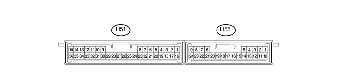
CHECK CERTIFICATION ECU (w/ Entry and Start System)
-
Disconnect the H51 ECU connector.
-
Measure the resistance and voltage according to the value(s) in the table below.
Terminal No. (Symbol) Wiring Color Terminal Description Condition Specified Condition H51-1 (+B) - Body ground W - Body ground Battery power supply Always 11 to 14 V H51-15 (E) - Body ground W-B - Body ground Ground Always Below 1 Ω If the result is not as specified, there may be a malfunction on the wire harness side.
-
-
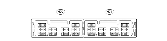
CHECK POWER MANAGEMENT CONTROL ECU (w/ Entry and Start System)
-
Disconnect the H71 ECU connector.
-
Measure the resistance and voltage according to the value(s) in the table below.
Terminal No. (Symbol) Wiring Color Terminal Description Condition Specified Condition H71-1 (AM22) - Body ground L - Body ground Battery power supply Always 11 to 14 V H71-2 (AM21) - Body ground B - Body ground Battery power supply Always 11 to 14 V H71-6 (GND) - Body ground W-B - Body ground Ground Always Below 1 Ω H71-5 (GND2) - Body ground W-B - Body ground Ground Always Below 1 Ω
-
-
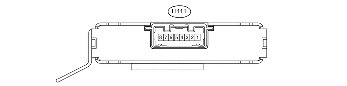
CHECK ID CODE BOX (w/ Entry and Start System)
-
Disconnect the H111 box connector.
-
Measure the resistance and voltage according to the value(s) in the table below.
Terminal No. (Symbol) Wiring Color Terminal Description Condition Specified Condition H111-1 (+B) - Body ground W - Body ground Battery power supply Always 11 to 14 V H111-8 (GND) - Body ground BR - Body ground Ground Always Below 1 Ω If the result is not as specified, there may be a malfunction on the wire harness side.
-
-
CHECK STEERING LOCK ACTUATOR ASSEMBLY (w/ Entry and Start System)

-
Disconnect the H54 actuator connector.
-
Measure the resistance and voltage according to the value(s) in the table below.
Terminal No. (Symbol) Wiring Color Terminal Description Condition Specified Condition H54-7 (B) - Body ground L - Body ground Battery power supply Always 11 to 14 V H54-1 (GND) - Body ground W-B - Body ground Ground Always Below 1 Ω If the result is not as specified, there may be a malfunction on the wire harness side.
-
-
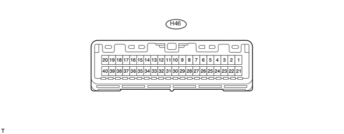
CHECK AIR CONDITIONING AMPLIFIER ASSEMBLY (for Automatic Air Conditioning System)
-
Disconnect the H46 amplifier connector.
-
Measure the resistance and voltage according to the value(s) in the table below.
Terminal No. (Symbol) Wiring Color Terminal Description Condition Specified Condition H46-1 (IG+) - Body ground Y - Body ground IG power supply Ignition switch off Below 1 V H46-1 (IG+) - Body ground Y - Body ground IG power supply Ignition switch ON 11 to 14 V H46-21 (B) - Body ground W - Body ground Battery power supply Always 11 to 14 V H46-14 (GND) - Body ground W-B - Body ground Ground Always Below 1 Ω If the result is not as specified, there may be a malfunction on the wire harness side.
-
-
CHECK AIR CONDITIONING CONTROL ASSEMBLY (for Automatic Air Conditioning System)

-
Disconnect the H21 control connector.
-
Measure the resistance and voltage according to the value(s) in the table below.
Terminal No. (Symbol) Wiring Color Terminal Description Condition Specified Condition H21-2 (IG+) - Body ground R - Body ground IG power supply Ignition switch off Below 1 V H21-2 (IG+) - Body ground R - Body ground IG power supply Ignition switch ON 11 to 14 V H21-5 (GND) - Body ground BR - Body ground Ground Always Below 1 Ω If the result is not as specified, there may be a malfunction on the wire harness side.
-
-
CHECK RAIN SENSOR (w/ Rain Sensor)

-
Disconnect the Q5 sensor connector.
-
Measure the voltage according to the value(s) in the table below.
Terminal No. (Symbol) Wiring Color Terminal Description Condition Specified Condition Q5-3 (SIG) - Body ground P - Body ground IG power supply Ignition switch off Below 1 V Q5-3 (SIG) - Body ground P - Body ground IG power supply Ignition switch ON 11 to 14 V Q5-2 (ES) - Body ground LG - Body ground Ground Always Below 1 V If the result is not as specified, there may be a malfunction on the wire harness side.
-
-
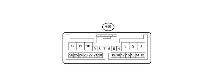
CHECK WINDSHIELD WIPER RELAY ASSEMBLY (w/ Rain Sensor)
-
Disconnect the H56 relay connector.
-
Measure the voltage and resistance according to the value(s) in the table below.
Terminal No. (Symbol) Wiring Color Terminal Description Condition Specified Condition H56-2 (IG) - Body ground L - Body ground IG power supply Ignition switch off Below 1 V H56-2 (IG) - Body ground L - Body ground IG power supply Ignition switch ON 11 to 14 V H56-12 (E) - Body ground BR - Body ground Ground Always Below 1 Ω If the result is not as specified, there may be a malfunction on the wire harness side.
-
-
CHECK DOUBLE LOCK DOOR CONTROL RELAY ASSEMBLY (w/ Double Locking System)

-
Disconnect the H50 relay connector.
-
Measure the voltage and resistance according to the value(s) in the table below.
Terminal No. (Symbol) Wiring Color Terminal Description Condition Specified Condition H50-7 (CPUB) - Body ground W - Body ground Battery power supply Always 11 to 14 V H50-1 (+B) - Body ground B - Body ground Battery power supply Always 11 to 14 V H50-14 (GND) - Body ground W-B - Body ground Ground Always Below 1 Ω If the result is not as specified, there may be a malfunction on the wire harness side.
-