TOYOTA PARKING ASSIST-SENSOR SYSTEM Clearance Sonar Main Switch Circuit
DESCRIPTION
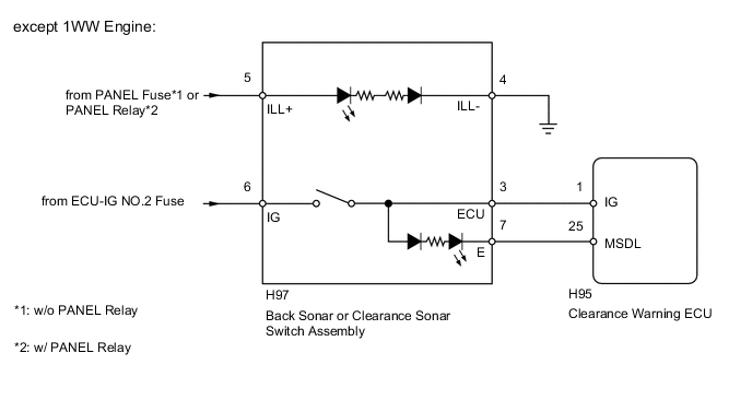
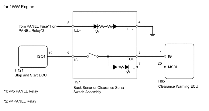
When the back sonar or clearance sonar switch assembly turns on, the on signal is input into the ECU.
WIRING DIAGRAM
CAUTION / NOTICE / HINT
Note
Inspect the fuses for circuits related to this system before performing the following inspection procedure.
PROCEDURE
-
CHECK SYMPTOMS
-
Check the symptoms.
Result Result Proceed to Back sonar or clearance sonar switch does not operate normally A Back sonar or clearance sonar switch operate normally, but the switch indicator does not illuminate A Back sonar or clearance sonar switch operate normally, but the indicator does not illuminate normally B
B 
INSPECT BACK SONAR OR CLEARANCE SONAR SWITCH ASSEMBLY Click here
A 
-
-
INSPECT BACK SONAR OR CLEARANCE SONAR SWITCH ASSEMBLY
-
Remove the back sonar or clearance sonar switch assembly Click here.
-
Measure the resistance according to the value(s) in the table below.
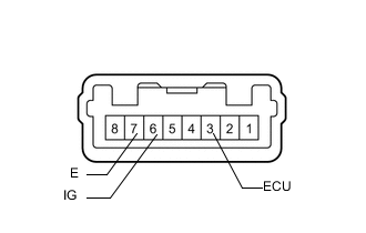
Standard Resistance Tester Connection Switch Condition Specified Condition 3 (ECU) - 6 (IG) Sonar switch on Below 1 Ω 3 (ECU) - 6 (IG) Sonar switch off 10 kΩ or higher -
Inspect the indicator operation.
OK Measurement Condition Specified Condition Battery positive (+) → Terminal 3 (ECU)
Battery negative (-) → Terminal 7 (E)
LED illuminates Result Result Proceed to OK (except 1WW Engine) A OK (for 1WW Engine) B NG C
B
CHECK HARNESS AND CONNECTOR (BACK SONAR OR CLEARANCE SONAR SWITCH - STOP AND START ECU) Click here
C 
REPLACE BACK SONAR OR CLEARANCE SONAR SWITCH ASSEMBLY Click here
A
-
-
CHECK HARNESS AND CONNECTOR (BACK SONAR OR CLEARANCE SONAR SWITCH - BATTERY)
-
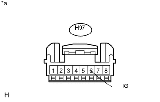
Text in Illustration *a Front view of wire harness connector
(to Back Sonar or Clearance Sonar Switch Assembly)
Disconnect the H97 back sonar or clearance sonar switch assembly connector.
-
Measure the voltage according to the value(s) in the table below.
Standard Voltage Tester Connection Switch Condition Specified Condition H97-6 (IG) - Body ground Ignition switch ON 11 to 14 V H97-6 (IG) - Body ground Ignition switch off Below 1 V
NG
REPAIR OR REPLACE HARNESS OR CONNECTOR
OK
-
-
CHECK HARNESS AND CONNECTOR (BACK SONAR OR CLEARANCE SONAR SWITCH - CLEARANCE WARNING ECU)
-
Disconnect the H97 back sonar or clearance sonar switch assembly connector.
-
Disconnect the H95 clearance warning ECU connector.
-
Measure the resistance according to the value(s) in the table below.
Standard Resistance Tester Connection Condition Specified Condition H97-3 (ECU) - H95-1 (IG) Always Below 1 Ω H97-7 (E) - H95-25 (MSDL) Always Below 1 Ω H97-3 (ECU) - Body ground Always 10 kΩ or higher H97-7 (E) - Body ground Always 10 kΩ or higher
OK
PROCEED TO NEXT SUSPECTED AREA SHOWN IN PROBLEM SYMPTOMS TABLE Click here
NG
REPAIR OR REPLACE HARNESS OR CONNECTOR
-
-
CHECK HARNESS AND CONNECTOR (BACK SONAR OR CLEARANCE SONAR SWITCH - STOP AND START ECU)
-
Disconnect the H97 back sonar or clearance sonar switch assembly connector.
-
Disconnect the H121 stop and start ECU connector.
-
Measure the resistance according to the value(s) in the table below.
Standard Resistance Tester Connection Condition Specified Condition H97-6 (IG) - H121-12 (IGO1) Always Below 1 Ω H97-6 (IG) - Body ground Always 10 kΩ or higher
NG
REPAIR OR REPLACE HARNESS OR CONNECTOR
OK
-
-
CHECK HARNESS AND CONNECTOR (BACK SONAR OR CLEARANCE SONAR SWITCH - CLEARANCE WARNING ECU)
-
Disconnect the H97 back sonar or clearance sonar switch assembly connector.
-
Disconnect the H95 clearance warning ECU connector.
-
Measure the resistance according to the value(s) in the table below.
Standard Resistance Tester Connection Condition Specified Condition H97-3 (ECU) - H95-1 (IG) Always Below 1 Ω H97-7 (E) - H95-25 (MSDL) Always Below 1 Ω H97-3 (ECU) - Body ground Always 10 kΩ or higher H97-7 (E) - Body ground Always 10 kΩ or higher
OK
PROCEED TO NEXT SUSPECTED AREA SHOWN IN PROBLEM SYMPTOMS TABLE Click here
NG
REPAIR OR REPLACE HARNESS OR CONNECTOR
-
-
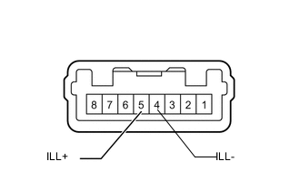
INSPECT BACK SONAR OR CLEARANCE SONAR SWITCH ASSEMBLY
-
Remove the back sonar or clearance sonar switch assembly Click here.
-
Inspect the indicator operation.
OK Measurement Condition Specified Condition Battery positive (+) → Terminal 5 (ILL+)
Battery negative (-) → Terminal 4 (ILL-)
LED illuminates
NG
REPLACE BACK SONAR OR CLEARANCE SONAR SWITCH ASSEMBLY Click here
OK
-
-
CHECK HARNESS AND CONNECTOR (BACK SONAR OR CLEARANCE SONAR SWITCH - BATTERY)
-
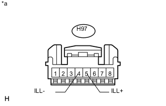
Text in Illustration *a Front view of wire harness connector
(to Back Sonar or Clearance Sonar Switch Assembly)
Disconnect the H97 back sonar or clearance sonar switch assembly connector.
-
Measure the voltage according to the value(s) in the table below.
Standard Voltage Tester Connection Switch Condition Specified Condition H97-5 (ILL+) - Body ground Ignition switch ON, light control switch tail or head 11 to 14 V H97-5 (ILL+) - Body ground Ignition switch off, light control switch off Below 1 V -
Measure the resistance according to the value(s) in the table below.
Standard Resistance Tester Connection Condition Specified Condition H97-4 (ILL-) - Body ground Always Below 1 Ω
OK
PROCEED TO NEXT SUSPECTED AREA SHOWN IN PROBLEM SYMPTOMS TABLE Click here
NG
REPAIR OR REPLACE HARNESS OR CONNECTOR
-