STEERING GEAR INSTALLATION
PROCEDURE
-
INSTALL TIE ROD END SUB-ASSEMBLY LH
-
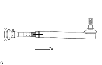
Text in Illustration *a Matchmark Install the lock nut and tie rod end sub-assembly to the steering gear so that the matchmarks align.
Tech Tips
After adjusting toe-in, tighten the lock nut to the specified torque.
-
-
INSTALL TIE ROD END SUB-ASSEMBLY RH
Tech Tips
Use the same procedures described for the LH side.
-
INSTALL STEERING GEAR ASSEMBLY
-
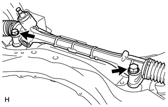
Install the steering gear to the front suspension crossmember with the 2 bolts and 2 nuts.
- Torque:
- 110 N*m { 1397 kgf*cm, 101 ft.*lbf }
Note
-
Make sure to tighten the bolts starting from the left side of the vehicle.
-
Because the nut has its own stopper, do not turn the nut. Tighten the bolt with the nut fixed in place.
-
-
INSTALL STEERING INTERMEDIATE SHAFT
-
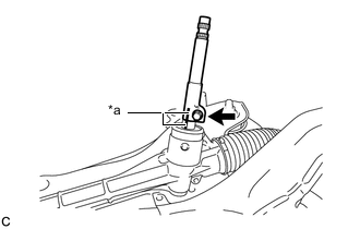
Text in Illustration *a Matchmark Align the matchmarks and install the steering intermediate shaft to the steering gear.
-
Install a new bolt.
- Torque:
- 35 N*m { 357 kgf*cm, 26 ft.*lbf }
-
-
INSTALL NO. 1 STEERING COLUMN HOLE COVER SUB-ASSEMBLY
-
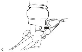
Align the round hole in the No. 1 steering column hole cover sub-assembly with the protrusion of the steering gear and install the cover.
-
-
INSTALL STEERING COLUMN HOLE SHIELD (w/ Steering Column Hole Shield)
-
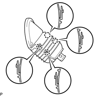
Engage the 4 claws to install the steering column hole shield to the No. 1 steering column hole cover .
-
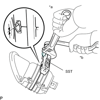
*a Hold *b Turn Using SST, install a new clamp on top of the steering column hole shield as shown in the illustration.
- SST
- 09521-24010
-
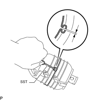
Using SST, measure the clearance.
- SST
- 09240-00020
Clearance 0.5 to 1.5 mm (0.0197 to 0.0590 in.)
-
-
INSTALL FRONT SUSPENSION CROSSMEMBER SUB-ASSEMBLY
-
INSTALL FRONT SUSPENSION MEMBER REAR BRACE LH
-
INSTALL FRONT SUSPENSION MEMBER REAR BRACE RH
-
CONNECT TIE ROD END SUB-ASSEMBLY LH
-
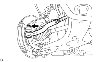
Connect the tie rod end to the steering knuckle with the nut.
- Torque:
- 49 N*m { 500 kgf*cm, 36 ft.*lbf }
Note
Tighten the nut up to an additional 60° if the holes for the cotter pin are not aligned.
-
Install a new cotter pin.
-
-
CONNECT TIE ROD END SUB-ASSEMBLY RH
Tech Tips
Use the same procedures described for the LH side.
-
INSTALL FRONT STABILIZER LINK ASSEMBLY LH
-
INSTALL FRONT STABILIZER LINK ASSEMBLY RH
Tech Tips
Use the same procedures described for the LH side.
-
INSTALL FRONT SUSPENSION MEMBER REINFORCEMENT LH
-
INSTALL FRONT SUSPENSION MEMBER REINFORCEMENT RH
-
INSTALL REAR ENGINE UNDER COVER LH
-
INSTALL REAR ENGINE UNDER COVER RH
-
INSTALL CENTER NO. 4 ENGINE UNDER COVER (for 1ZR-FAE, 2ZR-FAE)
-
INSTALL NO. 2 ENGINE UNDER COVER
-
INSTALL NO. 1 ENGINE UNDER COVER (for 1ZR-FAE, 2ZR-FAE)
-
INSTALL NO. 1 ENGINE UNDER COVER (for 1WW)
-
CONNECT NO. 1 STEERING COLUMN HOLE COVER SUB-ASSEMBLY
-
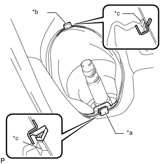
Text in Illustration *a Clip A *b Clip B *c Lip Attach clip B to the body and install the No. 1 steering column hole cover to the body with clip A.
Note
Make sure that the lip of the No. 1 steering column hole cover is not damaged.
-
-
CONNECT NO. 2 STEERING INTERMEDIATE SHAFT ASSEMBLY
-
INSTALL COLUMN HOLE COVER SILENCER SHEET
-
INSTALL FRONT WHEELS
- Torque:
- 103 N*m { 1050 kgf*cm, 76 ft.*lbf }
-
ADJUST FRONT WHEEL ALIGNMENT
-
Adjust the front wheel alignment Click here.
-