STEERING COLUMN ASSEMBLY REASSEMBLY
CAUTION / NOTICE / HINT
Note
When using a vise, do not overtighten it.
PROCEDURE
-
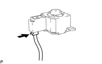
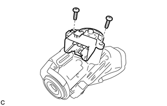
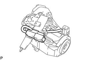
INSTALL STEERING LOCK ACTUATOR ASSEMBLY (w/ Entry and Start System)
-
Secure the steering column assembly in a vise.
-
Temporarily install the steering lock actuator assembly with a new tapered-head bolt.
Note
Be sure to use a new tapered-head bolt.
-
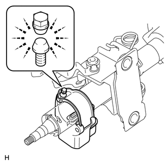
Tighten the tapered-head bolt until the bolt head breaks off.
-
-
INSTALL UNLOCK WARNING SWITCH ASSEMBLY (w/o Entry and Start System)
-
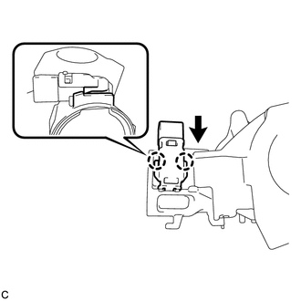
Attach the 2 claws to install the unlock warning switch assembly to the steering column upper bracket.
Tech Tips
Slide the unlock warning switch assembly in the direction indicate by the arrow in the illustration to install it.
-
-
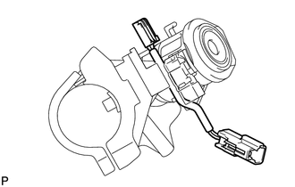
INSTALL IGNITION SWITCH LOCK CYLINDER ASSEMBLY (w/o Entry and Start System)
-
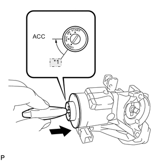
*1 LOCK Make sure that the ignition switch lock cylinder assembly is in the ACC position.
-
Install the ignition switch lock cylinder assembly to the steering column upper bracket.
-
Make sure that the ignition switch lock cylinder assembly is securely installed.
-
-
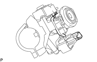
INSTALL TRANSPONDER KEY AMPLIFIER (w/o Entry and Start System)
-
Align the transponder key amplifier with the steering column upper bracket. Tilt the amplifier slightly and slide it into position.
-
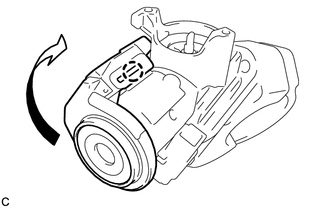
Push the transponder key amplifier to install it to the steering column upper bracket by engaging the 2 claws.
-
-
INSTALL IGNITION OR STARTER SWITCH ASSEMBLY (w/o Entry and Start System)
-
except Manual transaxle:
Install the key interlock solenoid.
-
Install the solenoid wire to the steering column upper bracket.
-
Connect the solenoid wire connector to the key interlock solenoid.
-
Install the key interlock solenoid to the steering column upper bracket with the 2 screws.
- Torque:
- 1.5 N*m { 15 kgf*cm, 13 in.*lbf }
-
-
Install the ignition or starter switch assembly to the steering column upper bracket with the 2 screws.
- Torque:
- 1.5 N*m { 15 kgf*cm, 13 in.*lbf }
-
except Manual transaxle:
Connect the solenoid wire connector to the ignition or starter switch assembly.
-
except Manual transaxle:
Make sure that the solenoid wire runs securely through the gap of the steering column upper bracket as shown in the illustration.
-
-
INSPECT STEERING LOCK OPERATION (w/o Entry and Start System)
-
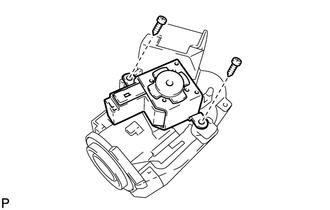
INSTALL STEERING COLUMN UPPER WITH SWITCH BRACKET ASSEMBLY (w/o Entry and Start System)
-
Secure the steering column assembly in a vise.
-
Temporarily install the steering column upper with switch bracket assembly to the steering column assembly with a new tapered-head bolt.
Note
Be sure to use a new tapered-head bolt.
-
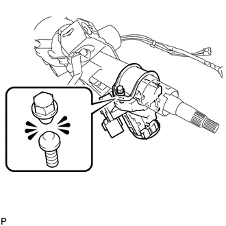
Tighten the tapered-head bolt until the bolt heads breaks off.
-
-
INSTALL POWER STEERING ECU ASSEMBLY