POWER STEERING SYSTEM, Diagnostic DTC:C1524, C1555
| DTC Code | DTC Name |
|---|---|
| C1524 | Motor Circuit Malfunction |
| C1555 | Motor Relay Welding Failure |
DESCRIPTION
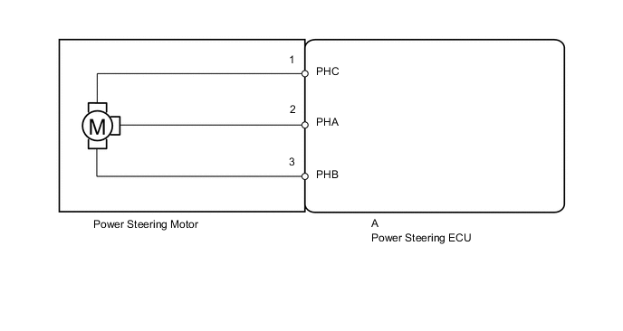
The power steering ECU supplies the current to the power steering motor through the motor circuit.
| DTC Code | DTC Detection Condition | Trouble Area |
|---|---|---|
| C1524 | A short or open in the motor circuit or abnormal voltage or current in the motor circuit. |
|
| C1555 | A motor relay malfunction. |
WIRING DIAGRAM
CAUTION / NOTICE / HINT
Note
If the power steering ECU assembly is replaced, perform the assist map writing Click here.
PROCEDURE
-
READ VALUE USING INTELLIGENT TESTER (MOTOR VOLTAGE)
-
Turn the ignition switch off.
-
Connect the intelligent tester to the DLC3.
-
Start the engine.
-
Turn the intelligent tester on.
-
Enter the following menus: Chassis / EMPS / Data List.
-
Select the items "Motor Terminal Volt (U)", "Motor Terminal Volt (V)" and "Motor Terminal Volt (W)" in the Data List and read the value displayed on the intelligent tester.
EMPS Tester Display Measurement Item/Range Normal Condition Diagnostic Note Motor Terminal Volt (U) Motor terminal voltage (U phase)/
Min.: 0.000 V
Max.: 98.000 V
Voltage between 1 V and approximately 1 V below battery voltage displayed The engine is running and the steering wheel is being turned. Motor Terminal Volt (V) Motor terminal voltage (V phase)/
Min.: 0.000 V
Max.: 98.000 V
Voltage between 1 V and approximately 1 V below battery voltage displayed The engine is running and the steering wheel is being turned. Motor Terminal Volt (W) Motor terminal voltage (W phase)/
Min.: 0.000 V
Max.: 98.000 V
Voltage between 1 V and approximately 1 V below battery voltage displayed The engine is running and the steering wheel is being turned. Result Result Proceed to When the steering wheel is turned, a voltage between 1 V and approximately 1 V below the battery voltage is displayed. A When the steering wheel is turned, a value other than the above is displayed. B
B 
REPLACE POWER STEERING ECU ASSEMBLY Click here
A 
-
-
CHECK CONNECTOR CONNECTION CONDITION (POWER STEERING MOTOR - POWER STEERING ECU)
-
Turn the ignition switch off.
-
Remove bus bar cover from the steering column assembly Click here.
-
Check that the metal contacts of the power steering ECU connector are securely connected to the metal contacts of the power steering motor, and that the screws are properly installed Click here.
OK The metal contacts of the power steering ECU connector are securely connected to the metal contacts of the power steering motor, and the screws are properly installed.
NG
SECURELY CONNECT POWER STEERING ECU TO POWER STEERING MOTOR Click here
OK
-
-
CHECK STEERING COLUMN ASSEMBLY
-
Remove the steering column assembly from the power steering ECU Click here.
-
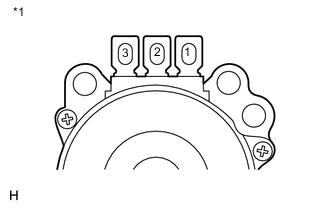
Text in Illustration *1 Component without power steering ECU
(Power Steering Motor)
Measure the resistance according to the value(s) in the table below.
Standard Resistance Tester Connection Condition Specified Condition 1 - 2 Always Below 1 Ω 1 - 3 Always Below 1 Ω 2 - 3 Always Below 1 Ω 1 - Body ground Always 10 kΩ or higher 2 - Body ground Always 10 kΩ or higher 3 - Body ground Always 10 kΩ or higher
OK
REPLACE POWER STEERING ECU ASSEMBLY Click here
NG
REPLACE STEERING COLUMN ASSEMBLY Click here
-