POWER STEERING SYSTEM, Diagnostic DTC:C1551
| DTC Code | DTC Name |
|---|---|
| C1551 | IG Power Supply Voltage Malfunction |
DESCRIPTION
The power steering ECU determines whether the ignition switch status is ON or off through the IG power supply circuit.
| DTC Code | DTC Detection Condition | Trouble Area |
|---|---|---|
| C1551 | An IG power supply circuit malfunction inside the ECU. |
|
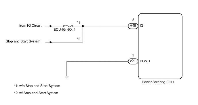
WIRING DIAGRAM
CAUTION / NOTICE / HINT
Note
-
If the power steering ECU assembly is replaced, perform the assist map writing Click here.
-
Inspect the fuses for circuits related to this system before performing the following inspection procedure.
PROCEDURE
-
READ VALUE USING INTELLIGENT TESTER (IG POWER SUPPLY)
-
Turn the ignition switch off.
-
Connect the intelligent tester to the DLC3.
-
Turn the ignition switch to ON.
-
Turn the intelligent tester on.
-
Enter the following menus: Chassis / EMPS / Data List.
EMPS Tester Display Measurement Item/Range Normal Condition Diagnostic Note IG Power Supply ECU power source voltage/
Min.: 0.0000 V
Max.: 20.1531 V
11 to 14 V The ignition switch is ON. OK The normal condition value is displayed the intelligent tester.
OK 
REPLACE POWER STEERING ECU ASSEMBLY Click here
NG 
-
-
CHECK HARNESS AND CONNECTOR (POWER STEERING ECU - BATTERY)
-
Turn the ignition switch off.
-
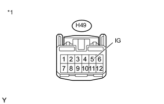
Text in Illustration *1 Front view of wire harness connector
(to Power Steering ECU)
Disconnect the H49 power steering ECU connector.
-
Turn the ignition switch to ON.
-
Measure the voltage according to the value(s) in the table below.
Standard Voltage Tester Connection Switch Condition Specified Condition H49-5 (IG) - Body ground Ignition switch ON 11 to 14 V Result Result Proceed to OK A NG w/o Stop and start system B w/ Stop and start system C
B
REPAIR OR REPLACE HARNESS OR CONNECTOR
C
GO TO STOP AND START SYSTEM (HOW TO PROCEED WITH TROUBLESHOOTING) Click here
A
-
-
CHECK GROUND BOLT AND WIRE HARNESS
-
Turn the ignition switch off.
-
Check that the ground bolt and wire harness are installed correctly Click here.
OK Ground bolt and wire harness are installed correctly.
NG
INSTALL GROUND BOLT AND WIRE HARNESS CORRECTLY Click here
OK
-
-
CHECK TERMINAL SCREW AND ECU WIRE SUB-ASSEMBLY
-
Remove the power terminal cover from the power steering ECU Click here.
-
Check that the z21 terminal screw and ECU wire sub-assembly are installed correctly Click here.
OK Terminal screw and ECU wire sub-assembly are installed correctly.
NG
INSTALL TERMINAL SCREW AND ECU WIRE SUB-ASSEMBLY CORRECTLY Click here
OK
-
-
CHECK ECU WIRE SUB-ASSEMBLY
-
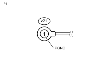
Text in Illustration *1 ECU Wire Sub-assembly Remove the z21 terminal screw from the power steering ECU Click here.
-
Measure the resistance according to the value(s) in the table below.
Standard Resistance Tester Connection Condition Specified Condition z21-1 (PGND) - Body ground Always Below 1 Ω
OK
REPLACE POWER STEERING ECU ASSEMBLY Click here
NG
REPLACE ECU WIRE SUB-ASSEMBLY Click here
-