BRAKE MASTER CYLINDER INSTALLATION
PROCEDURE
-
INSTALL BRAKE MASTER CYLINDER SUB-ASSEMBLY
-
Install a new O-ring to the brake master cylinder sub-assembly.
-
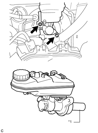
Text in Illustration *1 Piston Install the brake master cylinder with the 2 new nuts.
- Torque:
- 20 N*m { 204 kgf*cm, 15 ft.*lbf }
Note
-
The master cylinder requires careful handling. Do not allow the master cylinder to receive any impact, such as from being dropped. Do not reuse a master cylinder that has been dropped.
-
Do not strike or pinch the master cylinder piston, and do not cause any damage to the master cylinder piston by any other means.
-
When installing the master cylinder to the brake booster, or when removing the master cylinder from the brake booster, make sure that the master cylinder is kept horizontal or with its tip facing downward (the piston faces upward) to prevent the master cylinder piston from falling out.
-
Do not allow any foreign objects to contaminate the master cylinder piston. If a foreign object gets on the piston, remove it by using a piece of cloth and then apply an even layer of lithium soap base glycol grease around the circumference (sliding part) of the piston.
-
Do not use any other type of grease or fluid.
-
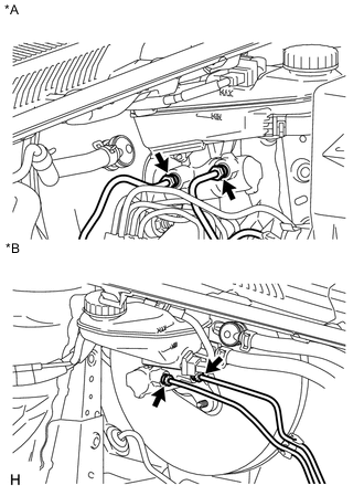
Text in Illustration *A for LHD *B for RHD Using a union nut wrench, connect the 2 brake lines to the brake master cylinder sub-assembly.
- Torque:
- 20 N*m { 199 kgf*cm, 14 ft.*lbf }
Note
Use the formula to calculate special torque values for situations where a union nut wrench is combined with a torque wrench Click here.
-
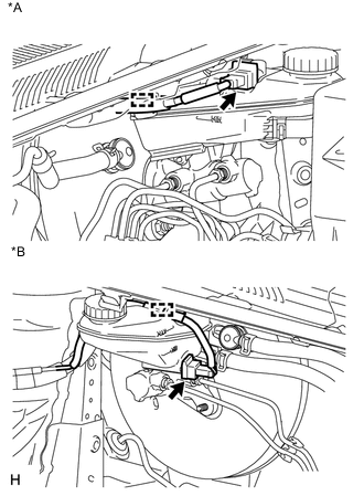
Text in Illustration *A for LHD *B for RHD Attach the clamp and connect the connector.
-
-
CONNECT CLUTCH TUBE (for Manual Transaxle)
-
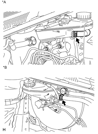
Text in Illustration *A for LHD *B for RHD Connect the clutch tube to the brake master cylinder reservoir assembly with the clip.
-
-
INSTALL BRAKE ACTUATOR ASSEMBLY
-
Install the brake actuator sub-assembly Click here.
-
-
INSTALL OUTER COWL TOP PANEL SUB-ASSEMBLY (for 1ZR-FAE)
-
INSTALL OUTER COWL TOP PANEL SUB-ASSEMBLY (for 2ZR-FAE)
-
INSTALL OUTER COWL TOP PANEL (for 1WW)
-
INSTALL WINDSHIELD WIPER MOTOR AND LINK
-
Install the windshield wiper motor and link Click here.
-
-
INSTALL NO. 2 CYLINDER HEAD COVER (for 1ZR-FAE)
-
INSTALL NO. 2 CYLINDER HEAD COVER (for 2ZR-FAE)
-
INSTALL FUEL FILTER ELEMENT ASSEMBLY (for 1WW)
-
Install the fuel filter element assembly Click here.
-
-
REMOVE CENTER COWL TOP VENTILATOR LOUVER
-
BLEED BRAKE SYSTEM
-
BLEED AIR FROM CLUTCH LINE (for 1ZR-FAE with Manual Transaxle)
-
BLEED AIR FROM CLUTCH LINE (for 2ZR-FAE with Manual Transaxle)
-
BLEED CLUTCH LINE (for 1WW)
-
INSTALL CENTER COWL TOP VENTILATOR LOUVER