TIRE PRESSURE WARNING SYSTEM TC and CG Terminal Circuit
DESCRIPTION
DTC output mode is set by connecting terminals 13 (TC) and 4 (CG) of the DLC3. The DTCs are output by the blinking of the tire pressure warning light.
WIRING DIAGRAM
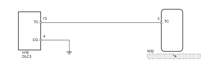
| *a | Tire Pressure Warning ECU and Receiver |
Tech Tips
When each warning light blinks continuously, a ground short in the wiring of terminal TC of the DLC3 or an internal ground short in each ECU is suspected.
PROCEDURE
-
CHECK HARNESS AND CONNECTOR (DLC3 - ECU AND BODY GROUND)
-
Disconnect the tire pressure warning ECU and receiver N32 connector.
-
Measure the resistance according to the value(s) in the table below.
Standard Resistance Tester Connection Condition Specified Condition H16-13 (TC) - N32-3 (TC) Always Below 1 Ω H16-13 (TC) or N32-3 (TC) - Body ground Always 10 kΩ or higher H16-4 (CG) - Body ground Always Below 1 Ω
OK 
PROCEED TO NEXT SUSPECTED AREA SHOWN IN PROBLEM SYMPTOMS TABLE Click here
NG
REPAIR OR REPLACE HARNESS OR CONNECTOR OR EACH ECU
-