VEHICLE STABILITY CONTROL SYSTEM, Diagnostic DTC:C1381
| DTC Code | DTC Name |
|---|---|
| C1381 | Acceleration Sensor Power Supply Voltage Malfunction |
DESCRIPTION
This DTC is stored when the skid control ECU (brake actuator assembly) receives a sensor supply voltage malfunction signal from the yaw rate and acceleration sensor (yaw rate sensor).
| DTC No. | DTC Detection Condition | Trouble Area |
|---|---|---|
| C1381 | Vehicle speed is 6 km/h (4 mph) or higher and yaw rate and acceleration sensor power supply malfunction signal is received for 1.1 seconds or more. |
|
WIRING DIAGRAM
Refer to DTCs C1234, C1243, C1244, C1245, C1418, C1472 and C1474 Click here.
CAUTION / NOTICE / HINT
Note
-
When replacing the yaw rate and acceleration sensor, perform acceleration sensor zero point calibration Click here.
-
Inspect the fuses for circuits related to this system before performing the following procedure.
PROCEDURE
-
CHECK TERMINAL VOLTAGE (IGA TERMINAL)
-
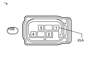
Text in Illustration *a Front view of wire harness connector
(to Yaw Rate and Acceleration Sensor (Yaw Rate Sensor))
Make sure that there is no looseness at the locking part and the connecting part of the connector.
-
Disconnect the H68 yaw rate and acceleration sensor (yaw rate sensor) connector.
-
Turn the ignition switch to ON.
-
Measure the voltage according to the value(s) in the table below.
Standard Voltage Tester Connection Condition Specified Condition H68-1 (IGA) - Body ground Ignition switch ON 11 to 14 V Result Result Proceed to OK A NG (w/o Stop and Start System) B NG (w/ Stop and Start System) C
B 
REPAIR OR REPLACE HARNESS OR CONNECTOR (IGA CIRCUIT)
C
INSPECT STOP AND START SYSTEM (BACKUP BOOST CONVERTER CIRCUIT) Click here
A 
-
-
CHECK HARNESS AND CONNECTOR (GNDA TERMINAL)
-
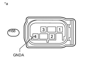
Text in Illustration *a Front view of wire harness connector
(to Yaw Rate and Acceleration Sensor (Yaw Rate Sensor))
Turn the ignition switch off.
-
Measure the resistance according to the value(s) in the table below.
Standard Resistance Tester Connection Condition Specified Condition H68-4 (GNDA) - Body ground Always Below 1 Ω Tech Tips
If troubleshooting has been carried out according to Problem Symptoms Table, refer back to the table and proceed to the next step Click here.
OK
REPLACE YAW RATE SENSOR Click here
NG
REPAIR OR REPLACE HARNESS OR CONNECTOR (GNDA CIRCUIT)
-